Method for forming liquid rubber composite node with damping through hole and node

A liquid rubber, damping hole technology, applied in the shock absorber-spring combination, spring/shock absorber design features, shock absorbers, etc. The effect of expanding the volume space

Active Publication Date: 2019-11-19
ZHUZHOU TIMES RUIWEI ANTI VIBERATION EQUIP LTD
View PDF12 Cites 16 Cited by
  • Summary
  • Abstract
  • Description
  • Claims
  • Application Information

AI Technical Summary

Problems solved by technology

[0009] In order to further optimize the performance of liquid rubber composite joints, the product needs to provide greater axial stiffness and achieve a larger dynamic-to-static ratio, so the existing liquid rubber composite joints in the above patent documents are difficult to achieve

Method used


Image

  • Method for forming liquid rubber composite node with damping through hole and node
  • Method for forming liquid rubber composite node with damping through hole and node
  • Method for forming liquid rubber composite node with damping through hole and node

Examples


Embodiment 1

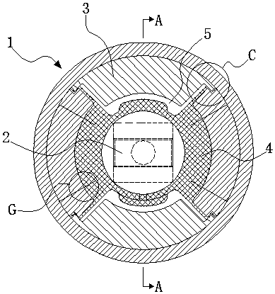
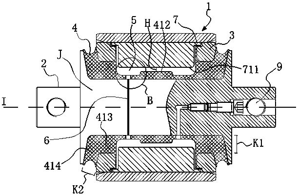
[0040] Embodiment 1: as figure 1 and figure 2 As shown, a method of forming a liquid rubber composite node with an intermediate damping hole, which is to add an intermediate spacer 3 between the outer casing 1 and the mandrel 2, and vulcanize and bond the intermediate spacer 3 and the mandrel 2 through rubber 4 Together, the integrated intermediate spacer and the mandrel are assembled into the outer casing 1; the mandrel 2 is provided with a damping through hole passing through the mandrel 2, and the middle spacer 3 is hollowed out to form multiple spaces. After vulcanization, the rubber 4 and the multiple spaces are used to form a plurality of liquid cavities 5 that are independent of each other. Liquids (not shown in the figure) are arranged in the plurality of liquid cavities 5 and pass through the plurality of liquid cavities 5. The damping through holes 6 communicate with each other. The liquid rubber composite joint formed by the above method can provide smaller radia...

Embodiment 2

[0055] Embodiment 2: as Figure 9 As shown, compared with Example 1, the difference is that in order to enable the liquid rubber to provide nonlinear stiffness characteristics, this embodiment adopts the following scheme: the inner peripheral arc surface of the arc-shaped cover plate 7 in this embodiment No bumps are set on the top, but a mandrel bump 211 is set on the mandrel 2, and the rubber 4 is covered on the mandrel 2 and the mandrel bump 211 and formed along it. Under the action of load, the arc-shaped cover plate 7 first contacts the rubber 4 located in the liquid cavity, and the node begins to provide nonlinear stiffness characteristics. The contact forms a hard stop limit protection function. In this embodiment, there are corresponding protruding mandrel protrusions 211 on the outer peripheral surface of the mandrel 2 corresponding to the two arc-shaped cover plates 7, and the two mandrel protrusions 211 are respectively located in the two liquid cavities. 5 in.

Embodiment 3

[0056] Embodiment 3: as Figure 10 As shown, compared with Embodiment 1, the difference is that in order to enable the liquid rubber to provide nonlinear stiffness characteristics, this embodiment adopts the following scheme: on the arc-shaped cover plate 7 and the mandrel 2 in this embodiment No projections are provided, and only rubber projections 415 protruding toward the arc-shaped cover plate 7 are provided on the rubber 4 covering the outer peripheral surface of the mandrel 2 in the liquid cavity. When using the arc-shaped cover plate 7 and the rubber projection 415 When in contact, the node begins to provide a non-linear stiffness characteristic, but in this embodiment, the node has no hard stop limit protection function. In this embodiment, the two rubber bumps 415 are respectively located in the two liquid cavities 5 .


PUM


Abstract

The invention discloses a method for forming a liquid rubber composite node with a damping through hole and the node. The forming method comprises the following steps that a middle spacer sleeve is additionally arranged between an outer sleeve and a mandrel, the middle spacer sleeve and the mandrel are bonded together through rubber vulcanization, and the middle spacer sleeve and the mandrel integrated are assembled into the outer sleeve; and the damping through hole penetrating through the mandrel is formed in the mandrel, a plurality of spaces are formed by hollowing in the middle spacer sleeve, after vulcanization, a plurality of liquid cavities mutually independent are formed by utilizing rubber and the plurality of spaces, and the plurality of liquid cavities are provided with liquid,and the plurality of liquid cavities communicate mutually through the damping through hole. According to the method for forming the liquid rubber composite node with the damping through hole and thenode, smaller radial stiffness and larger axial stiffness can be provided, and larger dynamic-static ratio can be achieved, so that the product performance of the liquid rubber composite node is optimized.

Description

technical field [0001] The invention relates to a method for forming a liquid rubber composite node and a node product, in particular to a method for forming a liquid rubber composite node with a damping through hole and the node. Background technique [0002] According to the dynamic requirements, when the pivoting arm node is running in a straight line at high speed (high frequency vibration), it provides a large radial stiffness to ensure the running stability and increase the critical speed; when it passes the curve (low frequency and large amplitude), it provides a small stiffness performance Guaranteed over-curve performance and reduced wear; it is difficult for ordinary joints to achieve the above characteristics, especially for old lines, where wheel rails and lines wear a lot, and the maintenance cost is high. Therefore, it is necessary to use a new product that has the above characteristics at the same time—liquid rubber composite joints. [0003] The working princ...

Claims


Application Information

Patent Timeline
Patent Type & Authority Applications(China)
IPC IPC(8): F16F13/14
CPCF16F13/14F16F13/1445F16F13/1409F16F13/1463F16F2230/06B29C65/02B29C66/71B29C66/742B29L2031/721F16F2226/04
Inventor 刘文松罗俊黄江彪张玉祥曾先会陈俊辉李静唐运轮
Owner ZHUZHOU TIMES RUIWEI ANTI VIBERATION EQUIP LTD
Why Eureka
Try Eureka