Edge sealing structure of water injection part of uniform temperature plate and its manufacturing method

A manufacturing method and vapor chamber technology, applied to lighting and heating equipment, indirect heat exchangers, etc., can solve the inconvenience of sealing the water injection pipe 31, break the working fluid and vacuum degree, and reduce the range or volume space of the vapor chamber 3 And other issues

Active Publication Date: 2020-05-22
ASIA VITAL COMPONENTS SHENZHEN CO LTD
View PDF5 Cites 0 Cited by
  • Summary
  • Abstract
  • Description
  • Claims
  • Application Information

AI Technical Summary

Problems solved by technology

[0003] see figure 1 , is the three-dimensional structure diagram of the existing vapor chamber, as shown in the figure, the vacuum water injection operation is mainly carried out through the water injection pipe body 31 during the manufacture of the chamber temperature chamber 3, and finally the end of the water injection pipe body 31 is shrunk. Closed to prevent vacuum leakage and working fluid leakage, the water injection pipe body 31 of the existing vapor chamber 3 is protruding and exposed outside the edge of the vapor chamber 3, which is quite easy to break due to impact during transportation and movement. Leakage of working fluid and vacuum occurs
[0004] see figure 2 , is another three-dimensional structure diagram of the existing vapor chamber, as shown in the figure, figure 2 The vapor chamber 3 is mainly composed of a first plate body 3a and a second plate body 3b correspondingly diffusion bonded to define a closed chamber (not shown in the figure), and the first and second plate bodies 3a, 3b are clamped Combined with a water injection pipe body 31, in order to improve the protruding of the aforementioned water injection pipe body 31 outside the edge of the vapor chamber, an inwardly recessed notch 32 is further provided, and then the water injection pipe body 31 is arranged there, and there is a professional Furthermore, a protective structure 32 is set up and down to clamp and protect the water injection pipe body 31, so as to protect the water injection pipe from being damaged by the impact of the water injection pipe 31, but the protective structure 32 hinders the sealing operation of the water injection pipe 31 to cause inconvenience, and the The setting of the notch and the protective structure 32 greatly reduces the range or volume space of the airtight chamber that the chamber 3 can set, thereby greatly reducing the heat transfer efficiency of the chamber 3
[0005] aforementioned figure 1 , figure 2 In addition to the above-mentioned shortcomings, the disclosed existing chamber structure has to sacrifice some blocks to reduce the working area of ​​the chamber 3 because the position where the water injection pipe body 31 is set is preserved, so how to solve the existing shortcomings is even more difficult Even canceling the setting of the water injection pipe body 31 is the primary goal of improvement for the people of the current art

Method used


Image

  • Edge sealing structure of water injection part of uniform temperature plate and its manufacturing method
  • Edge sealing structure of water injection part of uniform temperature plate and its manufacturing method
  • Edge sealing structure of water injection part of uniform temperature plate and its manufacturing method

Examples


Embodiment Construction

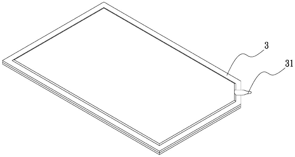
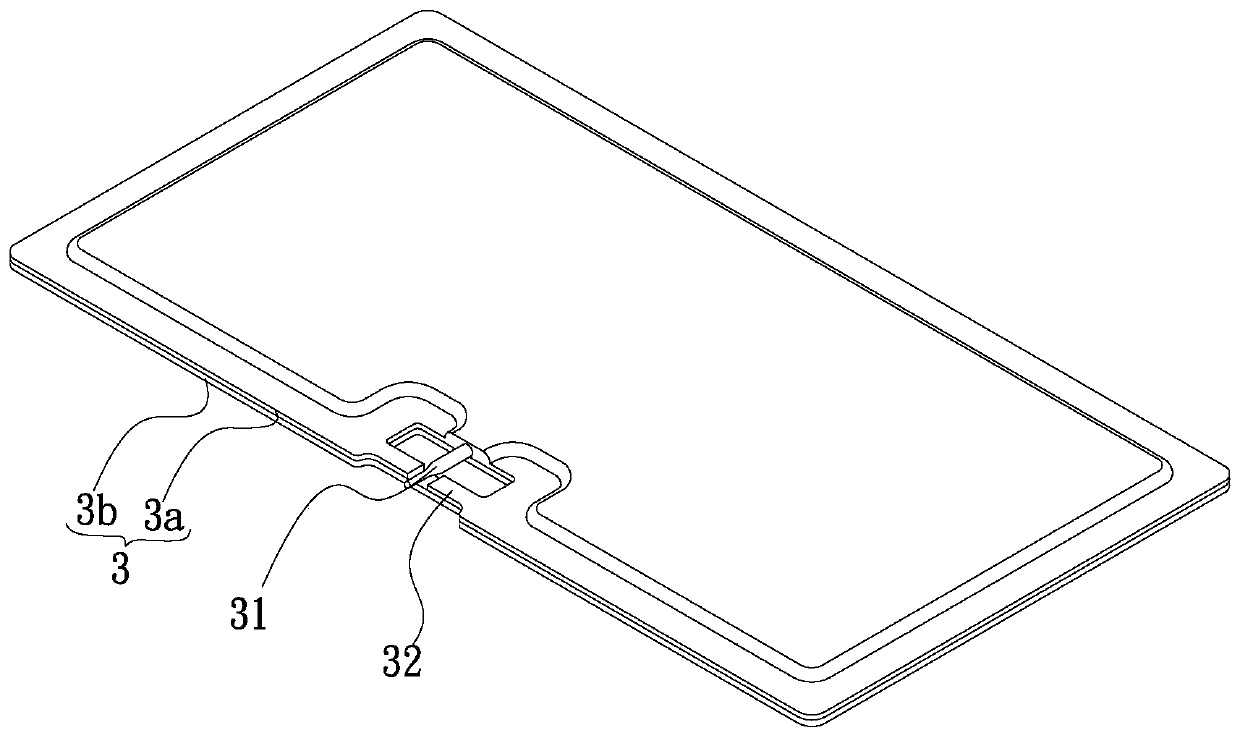
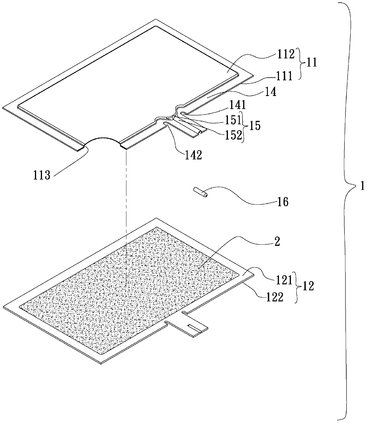
[0047] see image 3 , Figure 4 , is the three-dimensional disassembly and assembly diagram of the first embodiment of the edge sealing structure of the water injection part of the vapor chamber of the present invention. As shown in the figure, the edge sealing structure of the water injection part of the vapor chamber of the present invention includes: a body 1 and a capillary structure 2;

[0048] The body 1 has a first plate body 11 and a second plate body 12, and the first and second plate bodies 11, 12 are correspondingly covered to jointly define an airtight chamber 13, a water injection portion 15, and a lip 14 The ring is arranged on the outer edge of the main body 1 (that is, the outer edge ring of the first and second plates 11, 12 is provided with the lip 14), and the water injection part 15 has a water injection gap 151 and a water injection channel 152. One end of the water injection flow channel 152 is extended to connect with the lip 14, and the other end is conn...


PUM


Abstract

The invention provides a vapor chamber water injection part side seal structure and a making method thereof. The vapor chamber water injection part side seal structure comprises a body and a capillarystructure; the body is provided with a first plate body and a second plate body, the first plate body and the second plate body are correspondingly covered to jointly define an airtight cavity and awater injection part, a lip side is annularly arranged on the outer edge of the body, the water injection part is provided with a water injection gap and a water injection runner, the two ends of thewater injection runner are connected with the lip side and the water injection gap correspondingly so as to communicate with the airtight cavity, the portion, connected with the lip side, of the waterinjection runner is subject to press fit to be consistent with the height of the lip side or lower than the height of the lip side, and the capillary is selectively arranged on in the space of the airtight cavity of the body. Through the design and the making method of the structure, space of the inner cavity can be further increased, and the problem that the water injection portion protrudes outof the edge of the body and is prone to collision, and the water injection portion is damaged and loses energy is solved.

Description

technical field [0001] The invention relates to an edge sealing structure of a water injection part of a uniform temperature plate and a manufacturing method thereof, in particular to a uniform temperature that can improve the vapor-liquid circulation space of the inner chamber and prevent the water injection part from being easily damaged and disabled due to the protruding body edge. The edge sealing structure of the plate water injection part and its manufacturing method. Background technique [0002] Vapor chamber is a common heat dissipation structure at present. It mainly provides direct heat conduction between large areas and surfaces, and then provides rapid heat conduction effect from single or multiple heat sources. The principle of heat conduction of chamber is roughly the same as that of heat pipe, except that The board is mainly formed by two boards superimposed on each other for edge sealing to form a closed space, and a water injection pipe protruding from the ...

Claims


Application Information

Patent Timeline
Patent Type & Authority Patents(China)
IPC IPC(8): F28D15/02F28D15/04B23P15/00
CPCB23P15/00B23P2700/10F28D15/0283F28D15/04
Inventor 刘汉敏张健周小祥
Owner ASIA VITAL COMPONENTS SHENZHEN CO LTD
Why Eureka
Try Eureka