Image pickup apparatus with image pickup device and control method for image pickup apparatus

A technology of camera equipment and camera pixels, which is applied in image communication, color TV parts, TV system parts, etc., and can solve problems such as difficulty in balancing focus detection performance and camera performance, and camera performance degradation

Inactive Publication Date: 2014-03-26
CANON KK
View PDF3 Cites 10 Cited by
  • Summary
  • Abstract
  • Description
  • Claims
  • Application Information

AI Technical Summary

Problems solved by technology

[0007] However, in the case of accurately detecting the focus state of the imaging lens using the light incident surface phase difference method as described above, there will be a problem that, in the case of improving the focus detection performance, it will inevitably occur that the Decrease in camera performance for acquiring images
Therefore, it is difficult to achieve a balance between focus detection performance and imaging performance

Method used


Image

  • Image pickup apparatus with image pickup device and control method for image pickup apparatus
  • Image pickup apparatus with image pickup device and control method for image pickup apparatus
  • Image pickup apparatus with image pickup device and control method for image pickup apparatus

Examples


Embodiment Construction

[0025] Hereinafter, the present invention will be described in detail with reference to the accompanying drawings showing embodiments of the invention.

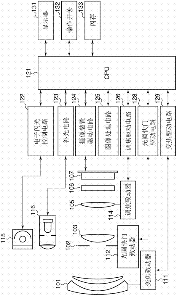
[0026] figure 1 is a block diagram schematically showing the configuration of a typical imaging apparatus having an imaging device according to an embodiment of the present invention.

[0027]The imaging apparatus shown in the figure is, for example, a digital camera, which has a first lens group 101 at the end of the imaging optical system. The first lens group 101 can move back and forth in the direction of the optical axis. An aperture shutter 102 is provided on the rear side of the first lens group 101, and the aperture shutter 102 adjusts the amount of light during shooting by adjusting its aperture, and also functions as an exposure time adjustment shutter during shooting of still images.

[0028] The second lens group 103 is provided on the rear side of the aperture shutter 102 . The aperture shutter 102 and the sec...


PUM


Abstract

An image pickup apparatus capable of making focus detection performance and image pickup performance compatible with each other. A plurality of image pickup pixels detect a subject image formed by an imaging optical system and generate an image for image pickup. Microlenses disposed for the respective image pickup pixels gather incident light to the respective image pickup pixels. Each image pickup pixel has a plurality of photoelectric converters divided in a first direction and a second direction perpendicular to the first direction. Each photoelectric converter photoelectrically converts each of subject images having passed through pupil partial areas corresponding to the respective photoelectric converters in an exit pupil of the imaging optical system and outputs focus detection signals for detecting a phase difference between the subject images. A first curvature of the microlenses in the first direction and a second curvature of the microlenses in the second direction are different.

Description

technical field [0001] The present invention relates to an imaging apparatus having an imaging device such as an image sensor and a control method thereof. Background technique [0002] As a method of detecting the focus state of an imaging lens in an imaging apparatus such as a digital camera, there is generally known a pupil division phase difference method (light incident surface phase difference method) using a two-dimensional imaging device in which microlenses are provided for each pixel. ). [0003] For example, according to U.S. Patent No. 4,410,804, a two-dimensional imaging device is used to detect the focus state of the imaging lens by using the light incident surface phase difference method. a photoelectric conversion unit. Here, a plurality of photoelectric conversion parts receive light in different regions of the exit pupil of the imaging lens via one microlens. Focus detection is performed using a light incident surface phase difference method by acquiring...

Claims


Application Information

Patent Timeline
Patent Type & Authority Applications(China)
IPC IPC(8): H04N5/232
CPCH04N5/23212H01L27/14623H01L27/14627H01L27/14621H04N23/56H04N23/672H04N23/73H04N25/704H04N25/134
Inventor 福田浩一
Owner CANON KK
Why Eureka
Try Eureka