Supercharge Your Innovation With Domain-Expert AI Agents!

Gear mechanism type centrifuge door lock

A gear mechanism and centrifuge technology, applied in the field of door locks, can solve problems such as inconvenient design and installation, and achieve the effect of convenient structure design and safe operation.

Inactive Publication Date: 2014-04-02
ANHUI USTC ZONKIA SCI INSTR
View PDF5 Cites 0 Cited by
  • Summary
  • Abstract
  • Description
  • Claims
  • Application Information

AI Technical Summary

Problems solved by technology

[0002] In the prior art, most of the door locks used to lock the centrifuge door cover and the body are locked by mechanical structure and electrical control, and manual push or electric mechanism is used to open and lock the door. The control mechanism of the door lock It must be designed on the side of the machine, which brings inconvenience to the design and installation of other components

Method used


Image

  • Gear mechanism type centrifuge door lock

Examples


Embodiment 1

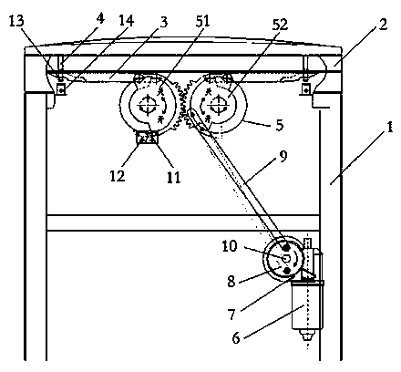
[0015] In order to improve the control degree of the automatic locking mechanism 5 and avoid the phenomenon that the latch 3 is inserted too deeply or insufficiently, a magnetic ring 11 can be installed on the circumference of the gear plate I51 and / or the gear plate II52, adjacent to the gear A position sensor 12 capable of sensing the magnetic ring 11 is installed on the disc I51 and / or the gear disc II52; a magnetic column 13 is installed at the bottom of the lock tongue 4, and a lock tongue sensor opposite to the magnetic column 13 is installed in the body 1 14. Both the position sensor 12 and the bolt sensor 14 are connected to the control system signal of the centrifuge.

[0016] When the magnetic column 13 is close to the deadbolt sensor 14, the output of the deadbolt sensor 14 changes from high level to low level under the action of the magnetic field. When the machine detects that the deadbolt sensor 14 all becomes low level, it shows that the door cover has been full...

Embodiment 2

[0019] The number of the gear discs can be adjusted according to the needs of use, so as to ensure that they can mesh with each other and be driven to rotate by the motor.


PUM


Abstract

The invention discloses a gear mechanism type centrifuge door lock comprising a body and a door cover. A pin is disposed on the top of the body. A bolt is disposed at the bottom of a door cover. An automatic locking mechanism used for automatically inserting the pin into the bolt is disposed inside the body. The automatic locking mechanism comprises a gear disc I connected to the push end of the pin. The gear disc I meshes with another gear disc II in the automatic locking mechanism. A motor is further disposed inside the body. A speed regulator is connected to an output shaft of the motor. A turning disc is arranged on the speed regulator and driven by the motor and the speed regulator to rotate so as to push the pin on the gear discs I and II into the bolt, and the body and the door cover are closed. The technical problems that the traditional door lock control mechanism needs to be mounted on the side of a centrifuge are solved; the gear mechanism type centrifuge door lock can be flexibly mounted and can be used under high safety coefficient.

Description

technical field [0001] The invention relates to a door lock, in particular to a door lock device for the safety protection of a centrifuge. Background technique [0002] In the prior art, most of the door locks used to lock the centrifuge door cover and the body are locked by mechanical structure and electrical control, and manual push or electric mechanism is used to open and lock the door. The control mechanism of the door lock It must be designed on the side of the machine, which brings inconvenience to the design and installation of other components. Contents of the invention [0003] The object of the present invention is to overcome the shortcomings of the above-mentioned prior art, and provide a gear mechanism type centrifuge door lock with simple structure, convenient use and flexible installation. [0004] A gear-mechanism type centrifuge door lock, including a body and a door cover, the top of the body is provided with a latch, and the bottom of the door cover i...

Claims


Application Information

Patent Timeline
IPC IPC(8): B04B7/00E05B65/00E05B47/06
Inventor 田杰唐俊标陈炯操和江张献明吴立佳林振兴崔杰张满
Owner ANHUI USTC ZONKIA SCI INSTR
Features
  • R&D
  • Intellectual Property
  • Life Sciences
  • Materials
  • Tech Scout
  • Unparalleled Data Quality
  • Higher Quality Content
  • 60% Fewer Hallucinations
Learn More