Bearing and driving mechanism for sliding door of urban rail vehicle

A technology of urban rail and driving mechanism, applied in the direction of power control mechanism, wing fan control mechanism, door/window fittings, etc. Problems such as long movement and force transmission routes, to achieve the effect of improving bearing capacity, facilitating replacement and maintenance, and stabilizing product quality

Active Publication Date: 2014-04-02
NANJING KANGNI MECHANICAL & ELECTRICAL
View PDF5 Cites 3 Cited by
  • Summary
  • Abstract
  • Description
  • Claims
  • Application Information

AI Technical Summary

Problems solved by technology

[0003] The technical problem solved by the present invention is to overcome the existing load-carrying drive mechanism for sliding doors, which takes up a lot of space, has a long transmission path of motion and force, wears out the screw nut pair quickly and has a short life, and produces a large impact noise between the load-carrying wheel and the slideway. There is no bearing capacity perpendicular to the direction of the door leaf, the intermediate screw support of the drive mechanism, and the problem of complicated replacement procedures

Method used


Image

  • Bearing and driving mechanism for sliding door of urban rail vehicle
  • Bearing and driving mechanism for sliding door of urban rail vehicle
  • Bearing and driving mechanism for sliding door of urban rail vehicle

Examples


Embodiment Construction

[0033] The present invention will be further described below in conjunction with the accompanying drawings.

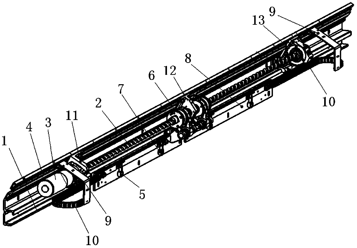
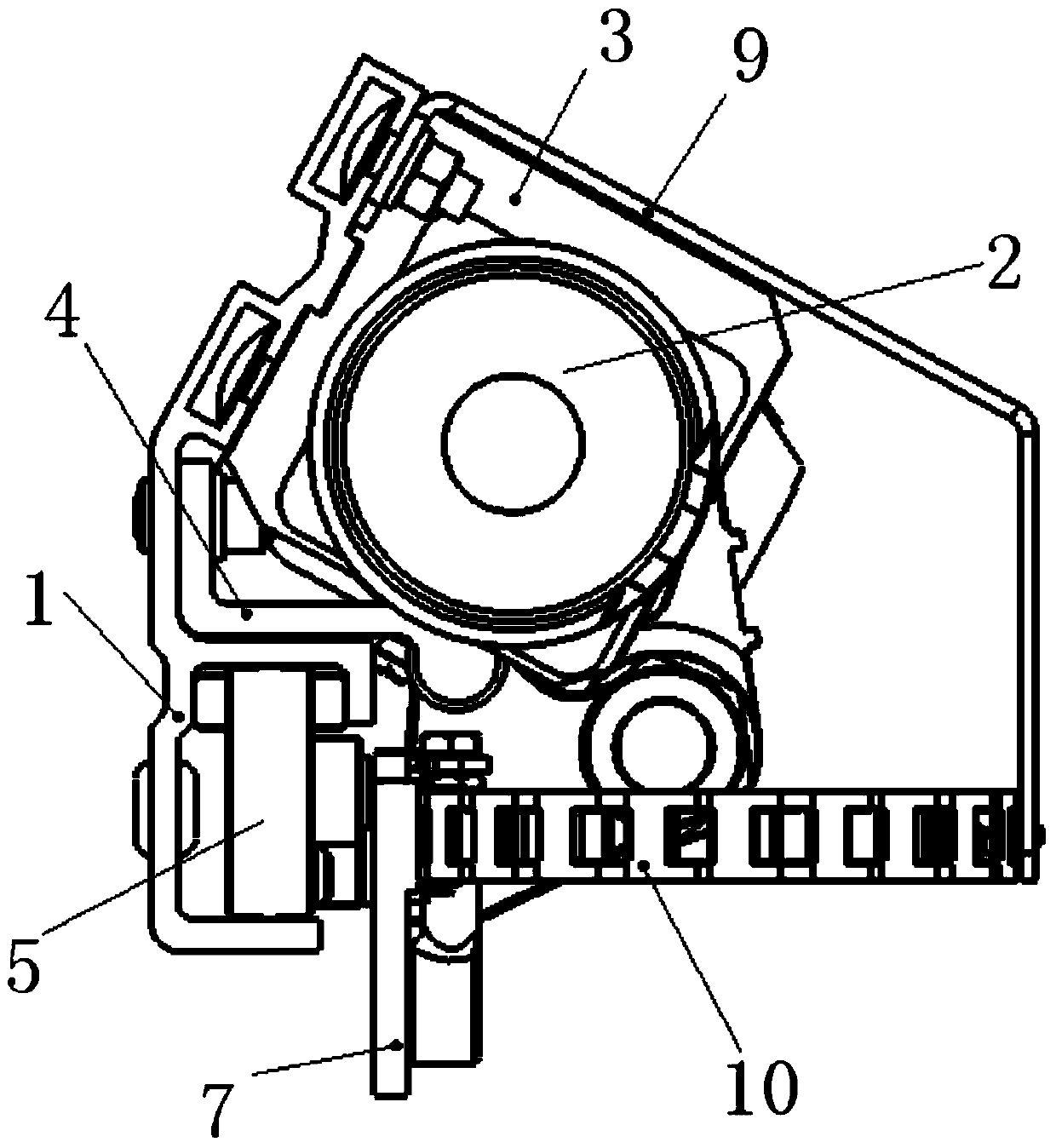
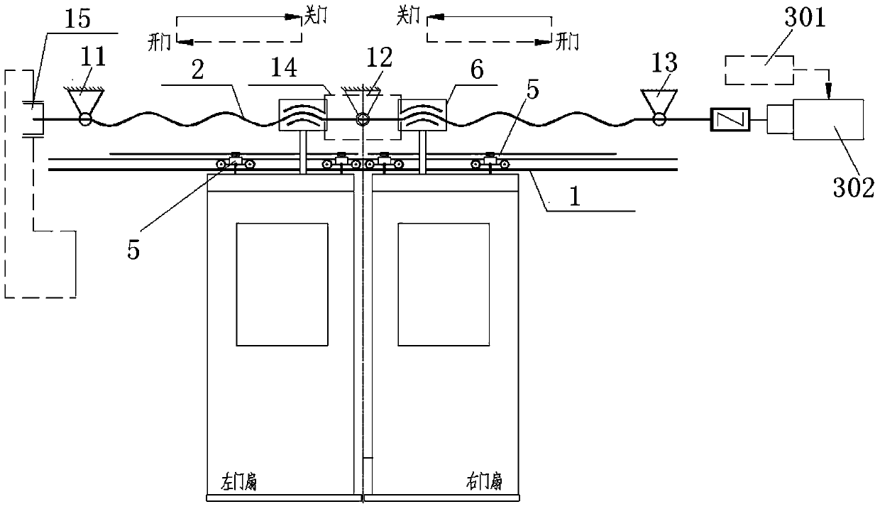
[0034] Such as figure 1 , figure 2 and image 3 As shown, the load-bearing drive mechanism for urban rail vehicle sliding doors of the present invention includes a slideway assembly 1, a drive screw 2, a screw drive assembly 3, a drive bracket 4, a load wheel 5, a left door leaf load bracket 7, a right door leaf carrying bracket 8, drag chain bracket 9 and drag chain 10,

[0035] Described driving screw mandrel 2 is installed in the inside of driving bracket 4, and one side of driving screw mandrel 2 is provided with screw mandrel driving assembly 3, and screw mandrel driving assembly 3 comprises driving motor 301 and sliding door controller 302, and sliding door controller 302 Control the rotation of the drive motor 301 to drive the drive screw 2 to rotate, and the high pair connection mechanism 6 on the drive screw 2 controls the left door leaf bearing bracket 7 ...


PUM


Abstract

The invention discloses a bearing and driving mechanism for a sliding door of an urban rail vehicle. The bearing and driving mechanism comprises a slideway component, a driving screw rod, a screw rod driving component, a driving support, a plurality of bearing wheels, a left-door-leaf bearing support, a right-door-leaf bearing support, drag chain supports and drag chains. The screw rod driving component is arranged on one side of the driving screw rod, and a manual unlocking device is arranged on the other side of the driving screw rod. The slideway component is mounted below the driving support. The bearing wheels are arranged in the slideway component. The left-door-leaf bearing support and the right-door-leaf bearing support are connected with one ends of the corresponding drag chains respectively, and the other ends of the drag chains are fixed on the drag chain supports respectively. The drag chain supports are fixed on the driving support. A front bearing piece, a middle bearing piece and a rear bearing piece are sleeved on the driving screw rod. Bearing capability of the bearing and driving mechanism is improved, abrasion of higher pair connecting mechanisms is reduced, service life of the driving screw rod is guaranteed, product quality is stabilized, product competiveness is improved, and the bearing and driving mechanism has good application prospect.

Description

technical field [0001] The invention relates to the technical field of urban rail vehicle components, in particular to a load-bearing driving mechanism for sliding doors of urban rail vehicles. Background technique [0002] With the rapid development of urban scale, urban rail transit can facilitate people's travel and has been widely used. At present, the sliding door load-bearing and driving structure used in urban rail vehicles are two different independent components, which occupy a large space. The force transmission route is long, and in the existing load-carrying drive mechanism, the connection between the screw nut pair and the door leaf under the load adopts the structural form of an H-shaped frame. The screw rod is a slender rod, and the screw rod bends and deforms after the nut is loaded. The H frame connecting the screw nut pair deviates from the theoretical position of the design, and the transmitted pushing force forms a non-90o included angle with the theoreti...

Claims


Application Information

Patent Timeline
Patent Type & Authority Applications(China)
IPC IPC(8): E05F15/14E05F17/00E05D13/00E05F15/652
Inventor 戴存曾世文丁瑞权顾孝青
Owner NANJING KANGNI MECHANICAL & ELECTRICAL
Why Eureka
Try Eureka