
Mandrel assembly for probe sub-section of induction logging tool and method of manufacturing the same

A logging instrument and inductive technology, which is used in electrical/magnetic detection, wellbore/well components, and measurement for logging records. Integrity effect

Inactive Publication Date: 2018-10-23
CNPC GREATWALL DRILLING ENG
View PDF7 Cites 0 Cited by
  • Summary
  • Abstract
  • Description
  • Claims
  • Application Information

AI Technical Summary

Problems solved by technology

There is currently no implementation of such a high-precision probe mandrel

Method used


Image

  • Mandrel assembly for probe sub-section of induction logging tool and method of manufacturing the same
  • Mandrel assembly for probe sub-section of induction logging tool and method of manufacturing the same
  • Mandrel assembly for probe sub-section of induction logging tool and method of manufacturing the same

Examples


Embodiment Construction

[0039] The present invention will be further described in detail in an exemplary manner below in conjunction with the accompanying drawings and specific embodiments.

[0040] Such as figure 1 As shown, the induction logging tool generally consists of an electronic circuit subsection 11, a preamplification subsection 12 and a probe subsection 13. These nipples are then connected upwards to other nipples in the logging tool string, and finally to the malic and logging cables to the surface acquisition system. The electronic circuit subsection 11 and the preamplification subsection 12 are equipped with power supply, transmission and acquisition circuits and communication circuits of the logging instrument. Sensors of logging tools are installed in the probe sub-section 13 . The electronic circuit short section 11 and the pre-amplification short section 12 are made of metal materials, and bear the external environmental pressure of 140Mpa; while the shell of the probe short sect...


PUM


Abstract

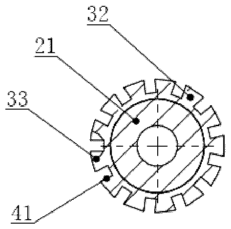
The invention relates to a mandrel assembly for an induction logging instrument probe nipple (13) and a manufacturing method thereof. The induction logging instrument probe nipple (13) comprises a coil antenna array (22) which is arranged along the axis of the mandrel assembly, wherein the coil antenna array (22) is formed by winding leads on an insulated substrate; the mandrel assembly comprises a mandrel (21) and a plurality of bushings (32) which are spaced axially; the bushings (32) are concentrically coated on the cylindrical outer surface of the mandrel (21); the insulated substrate is arranged on the bushings (32).

Description

technical field [0001] The invention relates to a well logging instrument, more particularly to a mandrel assembly of a short joint of a probe of an inductive well logging instrument and a manufacturing method thereof. Background technique [0002] Induction logging uses the principle of mutual inductance of alternating current, and uses the alternating current in the transmitting coil antenna to induce electromotive force in the receiving coil. Since both the transmitting coil antenna and the receiving coil antenna are in the well, the alternating current of the transmitting coil antenna must be in the formation around the wellbore. The eddy current is induced in the medium, and the eddy current affects the induced electromotive force of the receiving coil antenna, so the electromotive force is related to the strength of the eddy current, that is, to the conductivity of the formation. [0003] Array induction logging tools are developed on the basis of ordinary induction to...

Claims


Application Information

Patent Timeline
Patent Type & Authority Patents(China)
IPC IPC(8): G01V3/18E21B47/00
Inventor 谢昱北肖加奇姚春明朱瑞明
Owner CNPC GREATWALL DRILLING ENG
Learn More