

Sawtoothed angle regulation mechanism for two-dimensional spray pipe
A binary nozzle and angle adjustment technology, which is applied in the direction of machines/engines, jet propulsion devices, etc., can solve the problems of non-adjustable sawtooth angle and the influence of nozzle stealth performance, etc., and achieve less moving parts, simple structure, and stealth performance Good results
- Summary
- Abstract
- Description
- Claims
- Application Information
AI Technical Summary
Problems solved by technology
Method used
Image

Examples
Embodiment 1
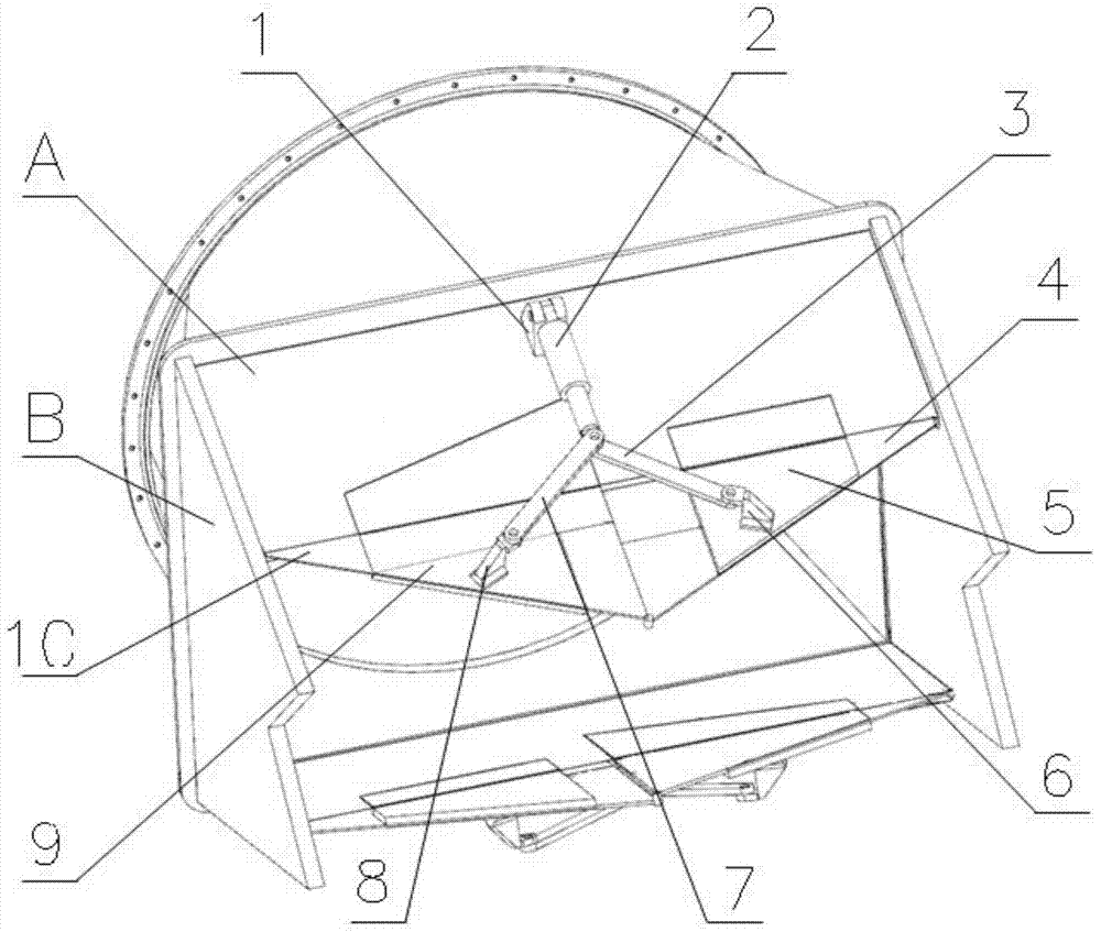
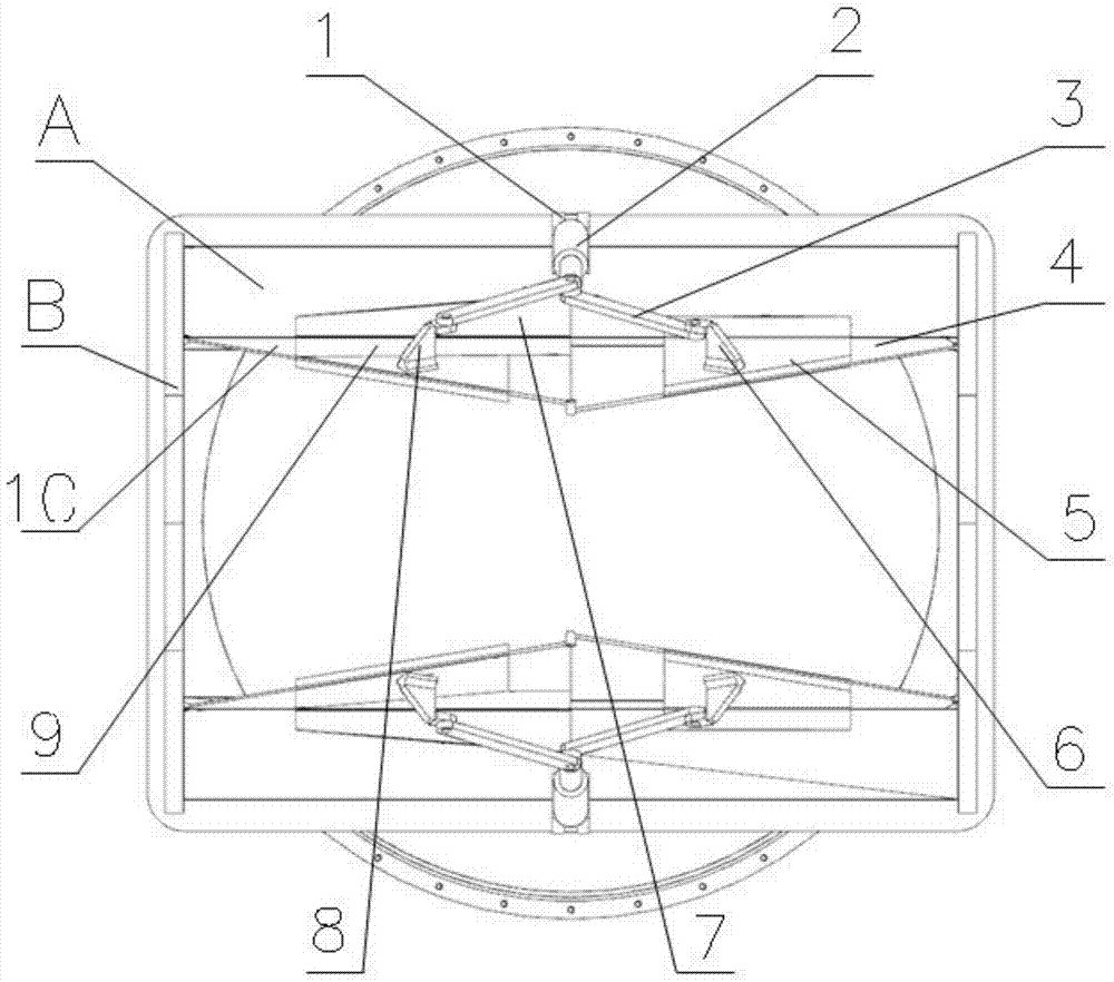
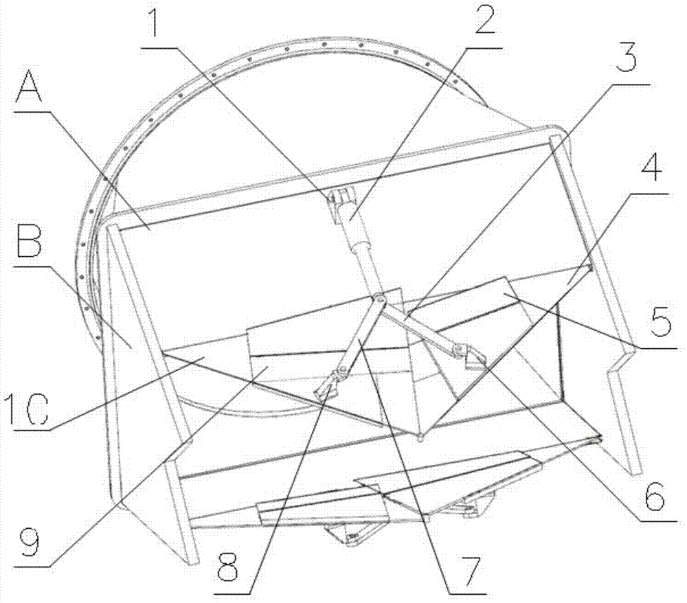
[0017] The present invention provides a binary nozzle sawtooth angle adjustment mechanism, which is characterized in that it includes a mounting base 1, an actuator 2, a pull rod 3, a right sealing plate 4, a right shielding plate 5, a mounting base 6, a pull rod 7, Mounting seat 8, left shielding plate 9 and left sealing plate 10, specifically:
[0018] The mounting base 1 is fixed on the convergence adjustment plate A of the binary nozzle; the side sealing baffle B is fixed on the left and right mounting sides of the round and rotating square cylinder; one end of the actuator 2 is connected with the mounting base 1, and the other end is connected with the rotating pair The tie rod 3 and the tie rod 7 are connected at the hinge; one end of the tie rod 3 and the tie rod 7 is hinged through a rotating pair, and the other end is respectively hinged with the mounting seat 6 and the mounting seat 8 through a rotating pair, and the rotating pair is kept vertical to the convergence a...
Embodiment 2
[0022] The present invention provides a binary nozzle sawtooth angle adjustment mechanism, which is characterized in that it includes a mounting base 1, an actuator 2, a pull rod 3, a right sealing plate 4, a right shielding plate 5, a mounting base 6, a pull rod 7, Mounting seat 8, left shielding plate 9 and left sealing plate 10, specifically:
[0023] The mounting base 1 is fixed on the convergence adjustment plate A of the binary nozzle; the side sealing baffle B is fixed on the left and right mounting sides of the round and rotating square cylinder; one end of the actuator 2 is connected with the mounting base 1, and the other end is connected with the rotating pair The tie rod 3 and the tie rod 7 are connected at the hinge; one end of the tie rod 3 and the tie rod 7 is hinged through a rotating pair, and the other end is respectively hinged with the mounting seat 6 and the mounting seat 8 through a rotating pair, and the rotating pair is kept vertical to the convergence a...
Embodiment 3
[0027] The present invention provides a binary nozzle sawtooth angle adjustment mechanism, which is characterized in that it includes a mounting base 1, an actuator 2, a pull rod 3, a right sealing plate 4, a right shielding plate 5, a mounting base 6, a pull rod 7, Mounting seat 8, left shielding plate 9 and left sealing plate 10, specifically:
[0028] The mounting base 1 is fixed on the convergence adjustment plate A of the binary nozzle; the side sealing baffle B is fixed on the left and right mounting sides of the round and rotating square cylinder; one end of the actuator 2 is connected with the mounting base 1, and the other end is connected with the rotating pair The tie rod 3 and the tie rod 7 are connected at the hinge; one end of the tie rod 3 and the tie rod 7 is hinged through a rotating pair, and the other end is respectively hinged with the mounting seat 6 and the mounting seat 8 through a rotating pair, and the rotating pair is kept vertical to the convergence a...
PUM
 Abstract
Description
Claims
Application Information