Sheet cage used for rolling bearing

A technology of rolling bearings and cages, used in bearing elements, shafts and bearings, mechanical equipment, etc.

Inactive Publication Date: 2014-04-02
SCHAEFFLER TECH AG & CO KG
View PDF13 Cites 8 Cited by
  • Summary
  • Abstract
  • Description
  • Claims
  • Application Information

AI Technical Summary

Problems solved by technology

Additionally, smaller radii in the corners of the cage p

Method used


Image

  • Sheet cage used for rolling bearing
  • Sheet cage used for rolling bearing
  • Sheet cage used for rolling bearing

Examples


Embodiment Construction

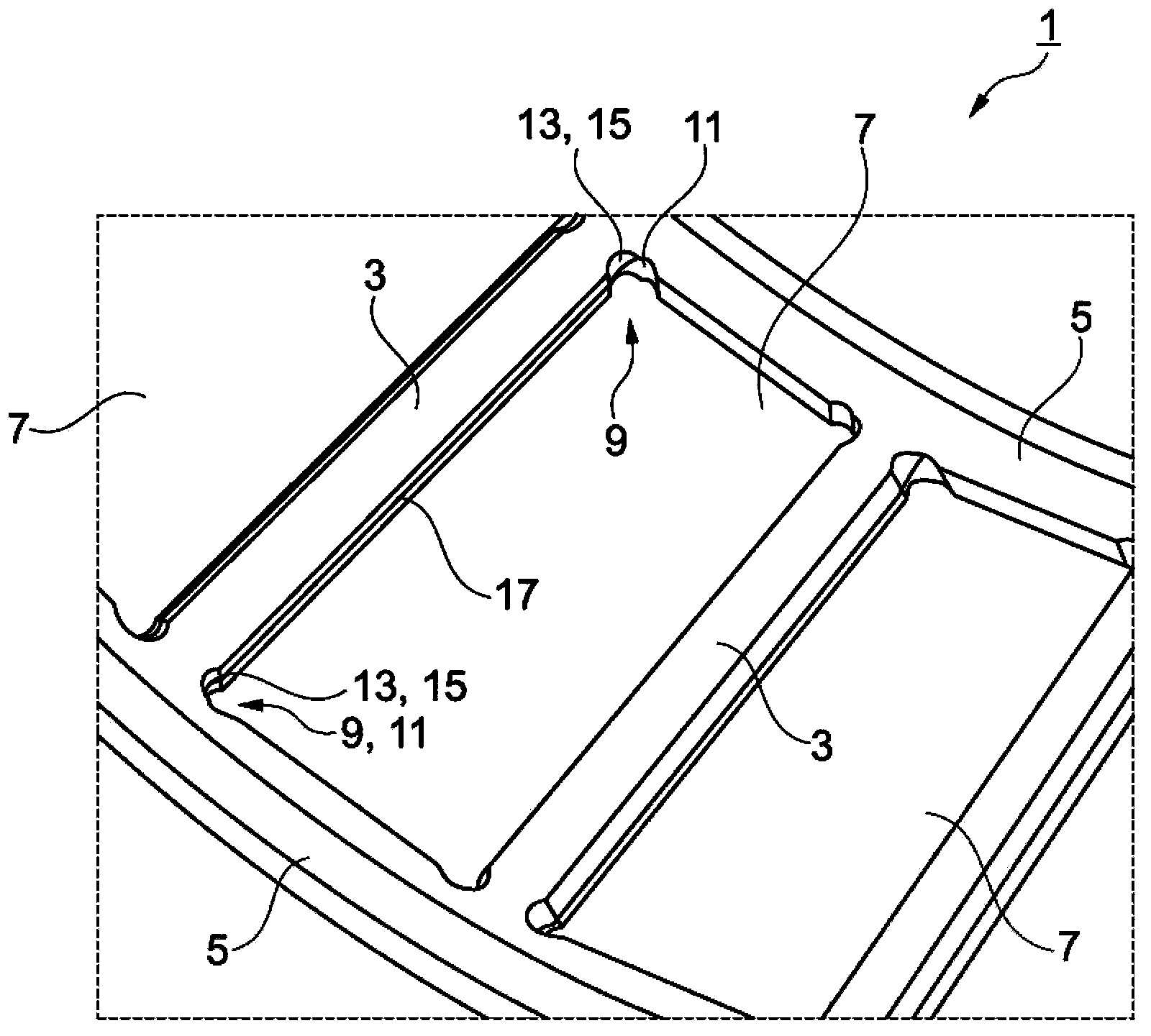
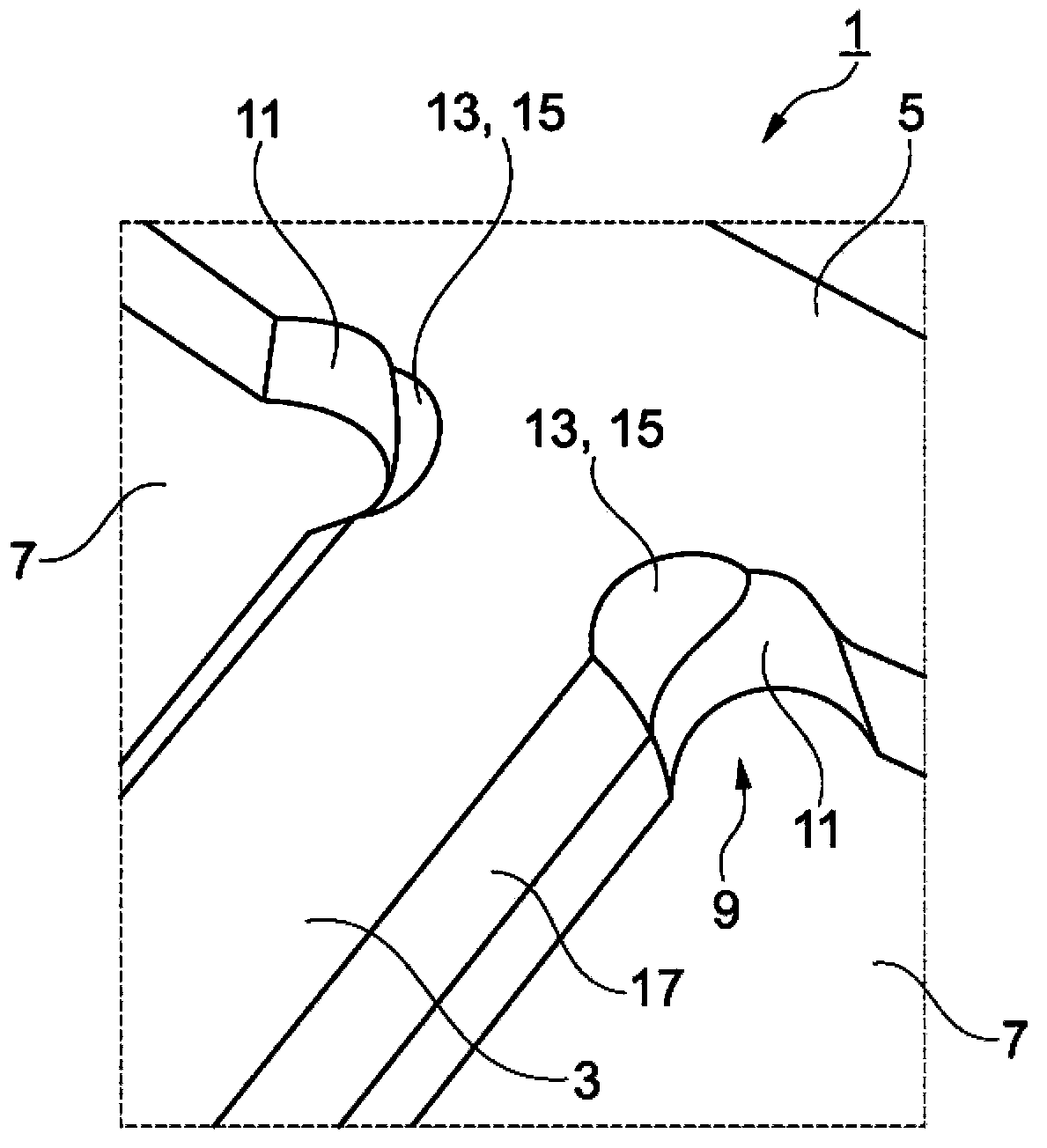
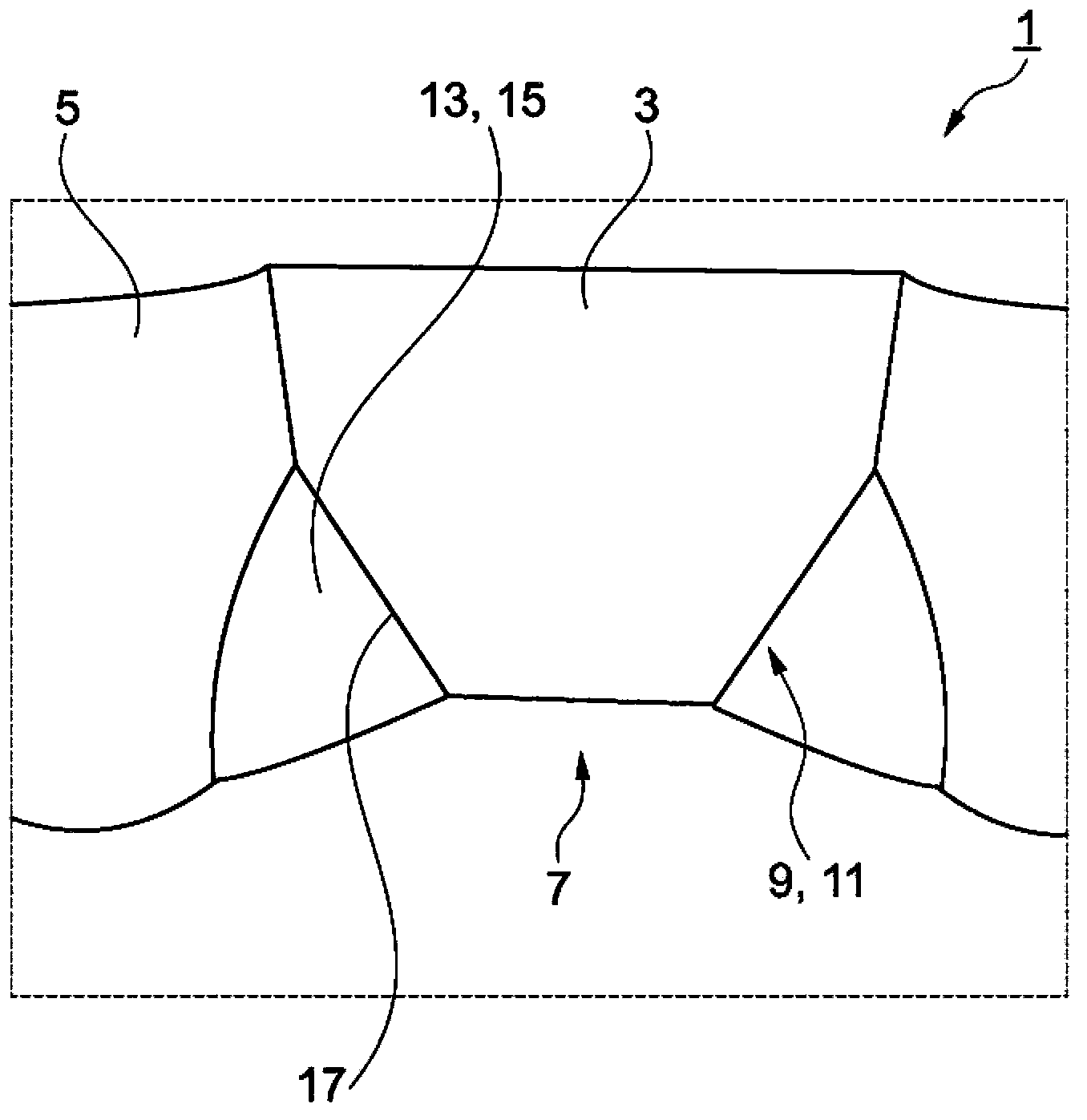
[0030] figure 1 A section of a cage 1 for roller-shaped rolling elements is shown in a three-dimensional view. Cage 1 is produced from sheet metal and consists of a number of webs 3 extending axially between two rings 5 ​​. Angled cage pockets 7 are formed in each case between two adjacent webs 3 and serve to accommodate the rolling bodies. rolling body in Figure 4 shown in .

[0031] Recesses 11 are in each case embossed into the corners 9 of the cage pockets 7 . The recess 11 serves for the rounding of the corner 9 . The recess 11 is widened inwardly in the radial direction by the bevel 13 . In this case, the bevel 13 is punched into the recess 11 starting from the inner periphery of the cage 1 . By stamping, the material of the cage 1 is plastically deformed in a targeted manner at the corners 9 of the cage pockets 7 , so that it is dense and does not have to be removed. The chamfer 13 can correspond accordingly to the installed rolling bodies.

[0032] All in all,...


PUM


Abstract

The invention relates to a sheet cage (1) used for a rolling bearing. The sheet cage is used for a roller-shaped rolling element, and comprises a certain quantity of connecting pieces (3) axially extending between rings (5), wherein a cage hole (7) used for accommodating a rolling element (19) is formed between each two adjacent connecting pieces (3), and recesses (11) used for rounding corners (9) are introduced into the corners (9) of the cage hole (7) in all radial directions. On this occasion, the rounded recesses (11) inwardly widen in the radial directions through inclined plant portions (13). The invention also relates to a method for making the sheet cage (1). The sheet cage guarantees the strength required by the connecting pieces in the case of increasing the radius of each of the recesses.

Description

technical field [0001] The invention relates to a sheet metal cage for rolling elements in the form of rollers, comprising a number of webs extending axially between rings, wherein between two adjacent webs each is formed for accommodating a rolling body A cage pocket with corners, and wherein recesses for rounding the corners are introduced radially in each case in the corners of the cage pocket. [0002] Furthermore, the invention relates to a method for producing a sheet metal cage for roller-shaped rolling elements. Background technique [0003] Sheet metal cages serve to accommodate and guide the rolling elements and are usually arranged for this purpose between two bearing rings of rolling bearings. The sheet metal cage must have sufficient strength to compensate radial and axial forces in the installed state of the rolling bearing, for example in a motor vehicle, in order to guide the rolling bodies without interference. In this case, the rolling elements are arrang...

Claims


Application Information

Patent Timeline
IPC IPC(8): F16C33/46
CPCF16C33/543F16C33/541
Inventor 亚历山大·舒尔茨孟宪伟
Owner SCHAEFFLER TECH AG & CO KG
Why Eureka
Try Eureka