
A flexible sliding wire device structure for a peripheral drive concentrator

A technology of peripheral transmission and device structure, applied in the field of concentrators, can solve the problems of easy corrosion, inconvenient maintenance and replacement, easy ignition, etc., and achieve the effect of improving installation efficiency

Active Publication Date: 2021-07-27
HUAIBEI ZHONGFEN MINING MACHINERY
View PDF3 Cites 0 Cited by
  • Summary
  • Abstract
  • Description
  • Claims
  • Application Information

AI Technical Summary

Problems solved by technology

[0004] The purpose of the present invention is to solve the problem that the existing current collector generally adopts a slip ring type current collector, which is composed of a collector ring and a brush frame. The cloth is exposed outside, and the phases are separated by insulating materials such as plastics. The exposed conductive metal surface of the collector ring on the central fixed support is relatively wide. This structure has the following problems: the demand for metal materials is large, The cost is high; the metal material of the conductor is exposed, which is prone to personal electric shock accidents; the metal material is easily corroded when exposed to the humid environment above the concentration tank for a long time, and its life is short, requiring frequent maintenance; the brush moves around the collector ring, This kind of contact movement is unstable, easy to spark, and easy to be broken down between phases; and the conductive metal block of the brush is usually installed on the sliding assembly by means of a flexible connector, so that the flexible connector and the brush conduct electricity When the metal block breaks down or is damaged, because the structure of the concentrator is relatively large and high, the staff is restricted by the area during the maintenance process, which makes it not convenient for maintenance and replacement. A flexible peripheral drive concentrator is proposed. Sliding device structure

Method used


Image

  • A flexible sliding wire device structure for a peripheral drive concentrator
  • A flexible sliding wire device structure for a peripheral drive concentrator
  • A flexible sliding wire device structure for a peripheral drive concentrator

Examples


Embodiment Construction

[0029] The technical solutions of the present invention will be clearly and completely described below in conjunction with the embodiments. Apparently, the described embodiments are only some of the embodiments of the present invention, not all of them. Based on the embodiments of the present invention, all other embodiments obtained by persons of ordinary skill in the art without creative efforts fall within the protection scope of the present invention.

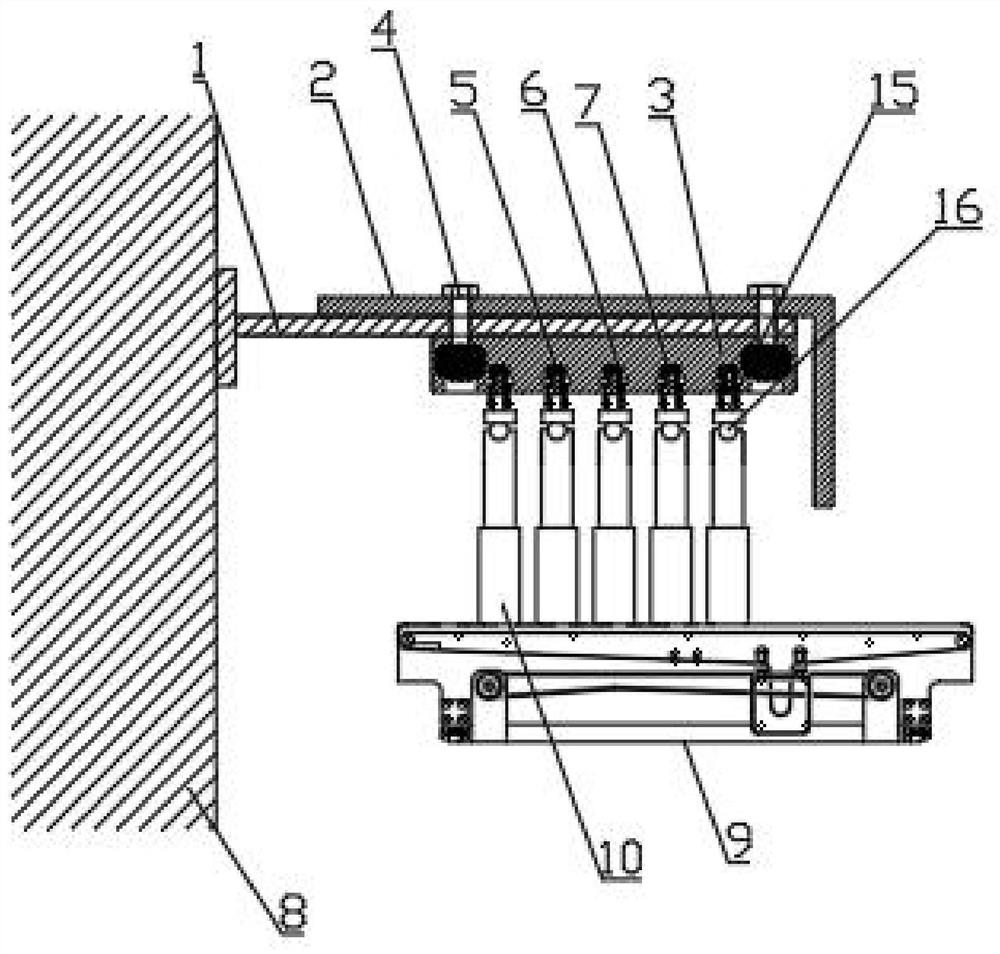
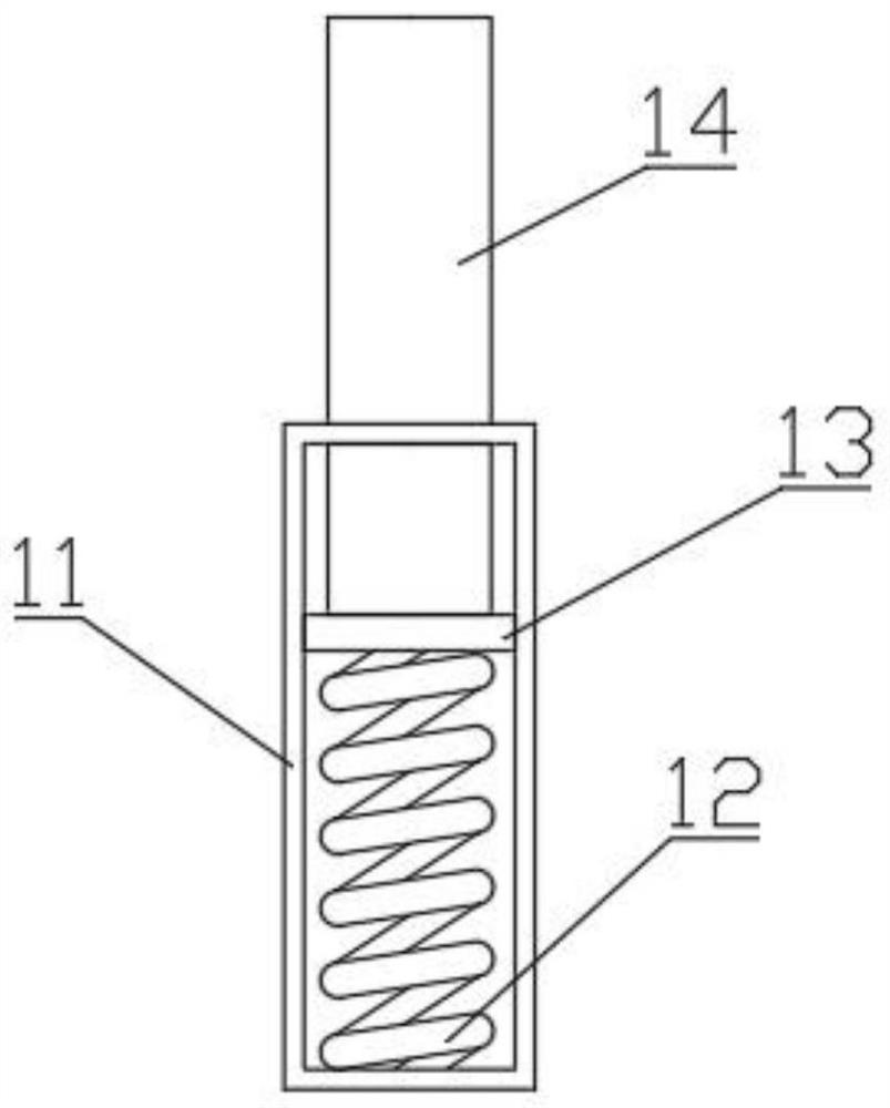
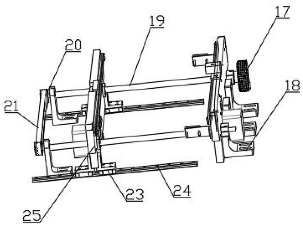
[0030] see Figure 1-6 As shown, a flexible sliding wire device structure of a peripheral transmission concentrator, including a safety sliding contact wire assembly fixing seat 1, an electric rail 6 and a flexible sliding wire device;

[0031] The safety trolley assembly fixing seat 1 is installed on the central fixed support 8, which is the central fixed support of the peripheral transmission concentrator, and the top surface of the safety trolley assembly fixing seat 1 is provided with a safety shield 2. An electric rai...


PUM


Abstract

The invention discloses a flexible sliding wire device structure for a peripheral transmission concentrator, which includes a safety sliding contact assembly fixing seat, an electric rail and a flexible sliding wire device; the safety sliding contact assembly fixing seat is installed on a central fixed support, and the safety sliding A safety shield is provided on the top surface of the fixed seat of the contact wire assembly, and an electric rail fixed seat is provided on the bottom surface of the fixed seat of the safety sliding contact assembly. , the bottom surface of the electric rail is connected with the flexible sliding wire device; the top surface of the sliding assembly is connected with the flexible connecting piece through the connecting piece, the top surface of the flexible connecting piece is connected with the conductive metal block of the brush through the brush support seat, and the conductive metal block of the brush It is located in the groove of the conductor metal material on the electric rail, and is slidably connected with the conductor metal material on the electric rail; the invention greatly improves the installation efficiency of the brush conductive metal block, and the contact movement mode achieves stable conduction and does not break The advantages of fire, phase and phase are not easy to be broken down.

Description

technical field [0001] The invention belongs to the technical field of concentrators, and relates to a structure of a flexible sliding wire device, in particular to a structure of a flexible sliding wire device for a peripheral transmission concentrator. Background technique [0002] When the peripheral transmission thickener is working normally, the slurry enters the steady flow barrel of the thickener through the material pipe, and then flows out through the lower part of the steady flow barrel and spreads to the surroundings of the thickener. During this process, the material gradually sinks by its own gravity. to the sloping pool bottom. [0003] The existing current collectors generally adopt slip ring type current collectors, which are composed of collector rings and brush holders. Most of the collector rings are arranged on the central fixed support from top to bottom and exposed outside. There are insulating materials such as plastics between them, and the exposed c...

Claims


Application Information

Patent Timeline
Patent Type & Authority Patents(China)
IPC IPC(8): H01R41/00
CPCH01R41/00
Inventor 杨冬周洋
Owner HUAIBEI ZHONGFEN MINING MACHINERY
Learn More