
Mop bucket with inner and outer bucket bodies

A mop bucket, inner and outer bucket technology, applied in the mop bucket field, can solve the problems of high cost, troublesome use, scratches on the ground, etc., and achieve the effects of reducing the floor space, being convenient to use, and improving the effect of shading

Pending Publication Date: 2019-10-29
NINGBO HAISHU LIANGPIN DAILY NECESSITIES CO LTD
View PDF1 Cites 0 Cited by
  • Summary
  • Abstract
  • Description
  • Claims
  • Application Information

AI Technical Summary

Problems solved by technology

[0004] 1. To clean the container, it is necessary to cooperate with the mop and its cleaning support device to realize cleaning, and to cooperate with its dehydration basket to realize dehydration, which is troublesome to use
[0005] 2. The wiper has a strip structure, and the wiper is evenly arranged and fixed along the mop head through the iron sheet. The operation of fixing the wiper is troublesome; the iron sheet is easy to rub against the ground, which will not only scratch the floor, but also affect the cleaning effect
[0007] 4. When cleaning and dehydrating, the central axis of the mop head and the central axis of the mop rod are on the same straight line, and the internal space of the cleaning container must be at least larger than the radial size of the two mop heads, so the cleaning container occupies a large space, packaging, high transportation costs
[0008] 5. It is not suitable to use disc-shaped wipes, because disc-shaped wipes need to open a through hole that allows the pole to pass through. During cleaning, stolen goods can easily enter the interior of the mop head through the through hole, causing damage to the mop

Method used


Image

  • Mop bucket with inner and outer bucket bodies
  • Mop bucket with inner and outer bucket bodies
  • Mop bucket with inner and outer bucket bodies

Examples


Embodiment Construction

[0043] In order to further explain the technical means and effects of the present invention to achieve the intended purpose of the invention, the specific implementation, structure, features and effects of the present invention will be described in detail below in conjunction with the accompanying drawings and preferred embodiments.

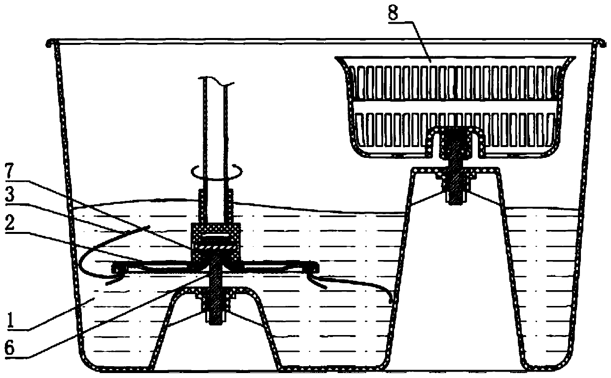
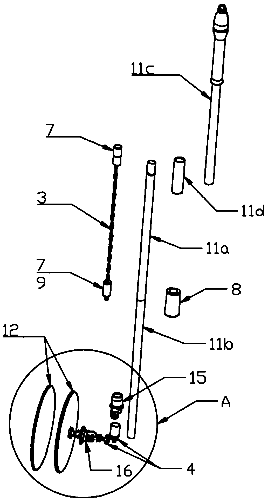
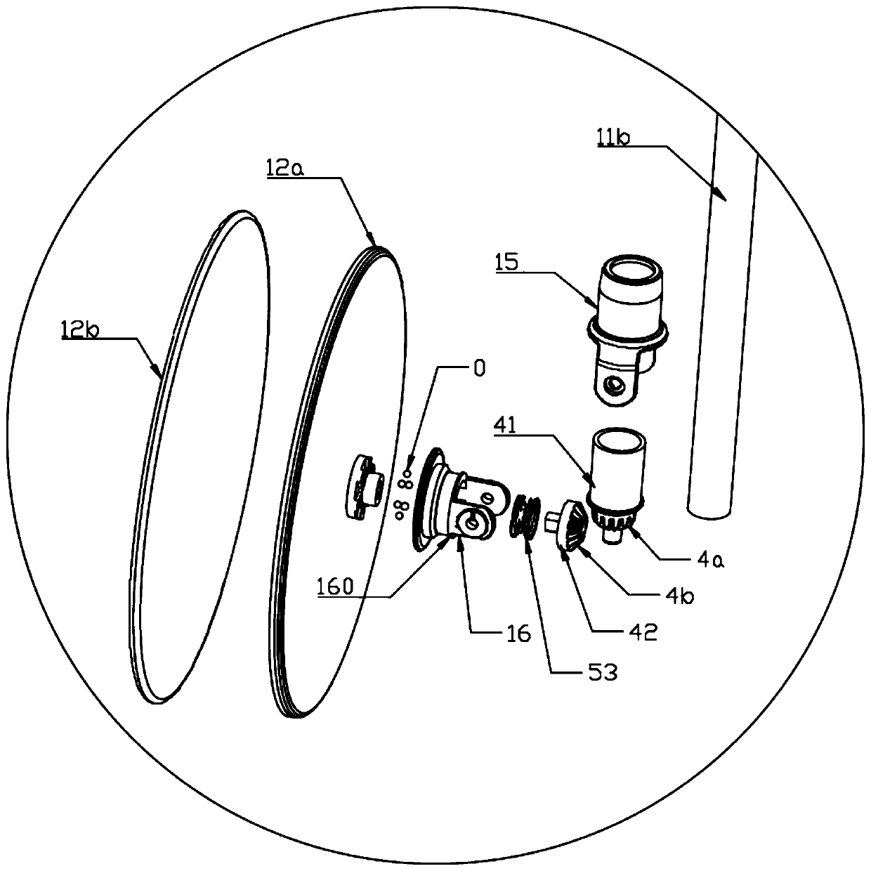
[0044] See Figure 2-7 , the mop bucket of the first embodiment of the present invention is used in conjunction with the corresponding mop 1, the mop 1 includes a mop rod 11 and a mop head 12 hinged to the lower end of the mop rod 11, the mop head 12 is a disc-shaped structure. The mop rod 11 is provided with a drive mechanism 3 for driving the rotation of the mop head 12, and a transmission mechanism 4 is provided between the mop rod 11 and the mop head 12. The mop rod 11 is pressed down to drive the drive mechanism 3, and the drive mechanism 3 passes through the transmission mechanism. 4 drives the mop head 12 to rotate. When the central axis ...


PUM


Abstract

The invention relates to the technical field of cleaning tools, in particular to a mop bucket with inner and outer bucket bodies. The mop bucket comprises a bucket body; the bucket body is provided with a cleaning and wringing area and a water storage area; the upper part, corresponding to the cleaning and wringing area, of the bucket body is provided with a first water baffle; the cleaning and wringing area is provided with a gap communicating with the water storage area above a tangent line of a mop head; water is transferred from the cleaning and wringing area to the water storage area through the gap and centrifugal force of rotation of the mop head; the gap is provided with a second water baffle; the first water baffle and the second water baffle are used for shielding water drops splashed when the mop head is cleaned and wrung; and a backflow channel for enabling the water to flow back from the water storage area to the cleaning and wringing area is arranged between the cleaningand wringing area and the water storage area. The mop bucket provided by the invention is provided with an inner bucket and an outer bucket, so that the cleaning and wringing area and the water storage area are formed; during use, the mop head is inserted into the inner bucket body, so that the mop head can be cleaned and wrung; and a mop does not need to move back and forth between a cleaning area and a wringing area, so that the mop bucket is convenient to use.

Description

technical field [0001] The invention relates to the technical field of cleaning tools, in particular to a mop bucket with inner and outer bucket bodies. Background technique [0002] At present, various mop structures are numerous. For example, the Chinese patent CN201798703U proposes a "mop cleaning device". In this technical solution, the mop cleaning device mainly includes a mop and a cleaning container. The mop head is hinged at the lower end of the mop rod. Wipes are arranged on the mop head, and a cleaning support device is arranged between the mop head and the cleaning container; The short drives the mop head to rotate, the cleaning support device supports the mop head to reduce the rotation resistance of the mop head, and the cleaning support device prevents the mop head from pressing the wipes at the same time. Since there is a cleaning support device between the mop head and the cleaning container, when cleaning, the mop head drives the wipes to rotate in the cle...

Claims


Application Information

Patent Timeline
Patent Type & Authority Applications(China)
IPC IPC(8): A47L13/58A47L13/20A47L13/258
CPCA47L13/58A47L13/20A47L13/258
Inventor 夏冬全
Owner NINGBO HAISHU LIANGPIN DAILY NECESSITIES CO LTD
Learn More