Solar breathing energy-saving device

An energy-saving device, solar energy technology, applied in solar thermal devices, solar thermal power generation, heating devices, etc., can solve the problems of high use and maintenance costs, high installation costs, waste of water resources, etc., and achieve long service life, reduced use and maintenance cost, water saving effect

Inactive Publication Date: 2014-04-02
NINGBO YILI TEWO TEXTILE MACHINERY
View PDF9 Cites 0 Cited by
  • Summary
  • Abstract
  • Description
  • Claims
  • Application Information

AI Technical Summary

Problems solved by technology

[0003] In order to solve the above-mentioned technical problems of waste of water resources, high installation cost, high use and maintenance cost, easy to freeze when the external temperature is low, and easy to deteriorate when the waterway is idle, the invention provides a solar energy breathing energy-saving device

Method used


Image

  • Solar breathing energy-saving device
  • Solar breathing energy-saving device
  • Solar breathing energy-saving device

Examples


Embodiment

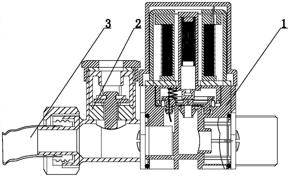
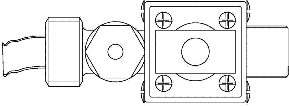
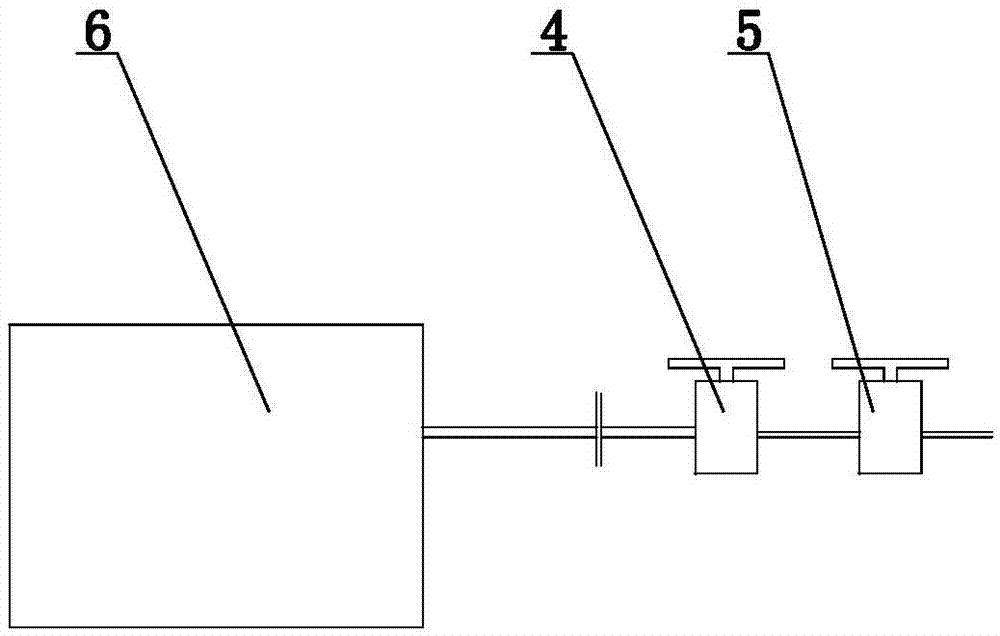
[0013] Such as figure 1 , 2 A solar breathing energy-saving device shown includes a water-saving mechanism A2, one end of the water-saving mechanism A2 is connected to the water outlet pipe 3, and the other end is connected to the water outlet of the solar energy 6, and the water-saving mechanism includes a valve body 1 and an electromagnetic Control terminal 7, the electromagnetic structure of the valve body 1 adopts a low-voltage power supply, which is 24V. The valve body 1 is provided with an electromagnetic structure that can control the waterway on-off of the water-saving mechanism A2. The water pipe 3 of the solar energy 6 water inlet is provided with There is a valve 4 and a main switch 5, and the valve 4 is a common valve.

[0014] During use, the original main switch 5 is installed at the user's use terminal, and then the valve 4 is installed on the main switch 5 sides nearby, and the valve 4 is on the side close to the solar energy 6. At this time, the valve 4 uses ...

Embodiment 2

[0019] The difference between this embodiment and Embodiment 1 is that the system installation method is that the valve 4 is directly installed on the water inlet of the solar energy 6, and the valve 4 is a water-saving mechanism B. At this time, only the cleaning button is turned on, the indicator light of the closing button is off, and the cleaning button The upper indicator light is always on or flashing. At this time, the control electromagnetic control terminal 7 controls the water-saving mechanism B to be closed, and the water-saving mechanism A2 is turned on, so that the water in the solar energy 6 is emptied. This operation can not only play a role in cleaning and When the external temperature is too low, the solar energy 6 and the water outlet pipe 3 are protected from being damaged by freezing, and it can also effectively prevent the internal water source from deteriorating when the solar energy system is idle, corroding equipment and harming human health. When normal...


PUM


Abstract

The invention relates to the field of water heaters, in particular to a solar breathing energy-saving device. The solar breathing energy-saving device comprises a water-saving mechanism A, wherein one end of the water-saving mechanism A is connected with a water outlet pipe, and the other end of the water-saving mechanism A is connected to the water outlet of a solar water heater; the water-saving mechanism comprises a valve body and an electromagnetic control terminal; an electromagnetic structure which can be used for controlling the switch-on / off of a water path of the water-saving mechanism A is arranged in the valve body. The solar breathing energy-saving device has the beneficial effects that water resources are saved, the installation, use and maintenance costs are reduced greatly, the cleanliness and sanitation of water resources in pipelines and the solar water heater can be ensured, a solar system is protected from being frozen to damage when the external air temperature is too low, and the service lives of the pipelines and solar equipment are prolonged. The solar breathing energy-saving device is economical and environment-friendly during use, and is easy to operate, and is user-friendly.

Description

technical field [0001] The invention relates to the field of water heaters, in particular to a solar energy breathing energy-saving device. Background technique [0002] Usually, there is a certain distance between the solar energy device and the water outlet of the user's terminal. This distance is basically connected with a water pipe. There is still some water in the water pipe after the current device is used. In this way, the user generally releases it when it is used next time. This part of water is especially prominent when the external temperature is low, causing waste; when the external temperature is low to a certain extent, the water in the water pipes and solar energy is very easy to freeze and crack the water pipes and solar cylinders. Therefore, the current solution is to install Water pipes made of anti-freeze materials and electric heating belts are installed on the outer surface of the water pipes, and thermal insulation devices are installed on the solar en...

Claims


Application Information

Patent Timeline
IPC IPC(8): F24J2/46
CPCY02E10/40
Inventor 尹帮富
Owner NINGBO YILI TEWO TEXTILE MACHINERY
Why Eureka
Try Eureka