Magnetic-inductive volumetric flow meter

A technology of flow measurement and electromagnetic induction, which is applied in the field of electromagnetic induction flow measuring instruments, can solve the problems of inability to distinguish reliably

Active Publication Date: 2014-04-02
IMF ELECTRONIC GMBH
View PDF10 Cites 4 Cited by
  • Summary
  • Abstract
  • Description
  • Claims
  • Application Information

AI Technical Summary

Problems solved by technology

In addition to the problem that the measurement of the flow can be influenced by the measurement or determination of the fill level, especially when measuring electrodes primarily provided for the flow measurement are included in the measurement, there is also the problem that for the measured value of the fill level the The different measuring principles depend on the conductivity of the medium, which must therefore be known in order to be able to report on the fill level
In addition, the measurement of the fill level can be influenced by a thin liquid film or conductive buildup in the area of ​​the measuring device, so that it cannot be reliably distinguished whether "only" medium adhesion is involved or a correspondingly high enough fill level is present

Method used


Image

  • Magnetic-inductive volumetric flow meter
  • Magnetic-inductive volumetric flow meter
  • Magnetic-inductive volumetric flow meter

Examples


Embodiment Construction

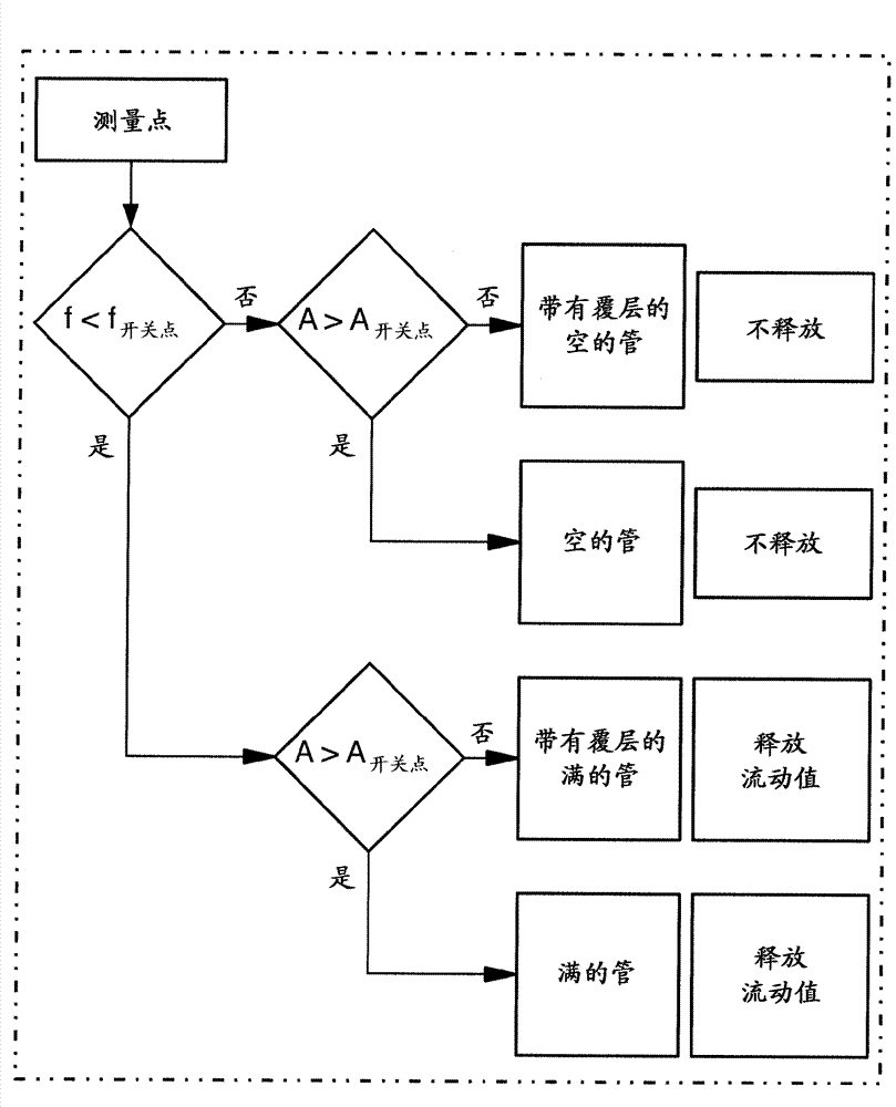
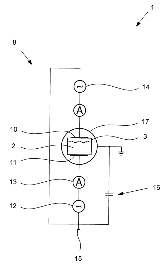
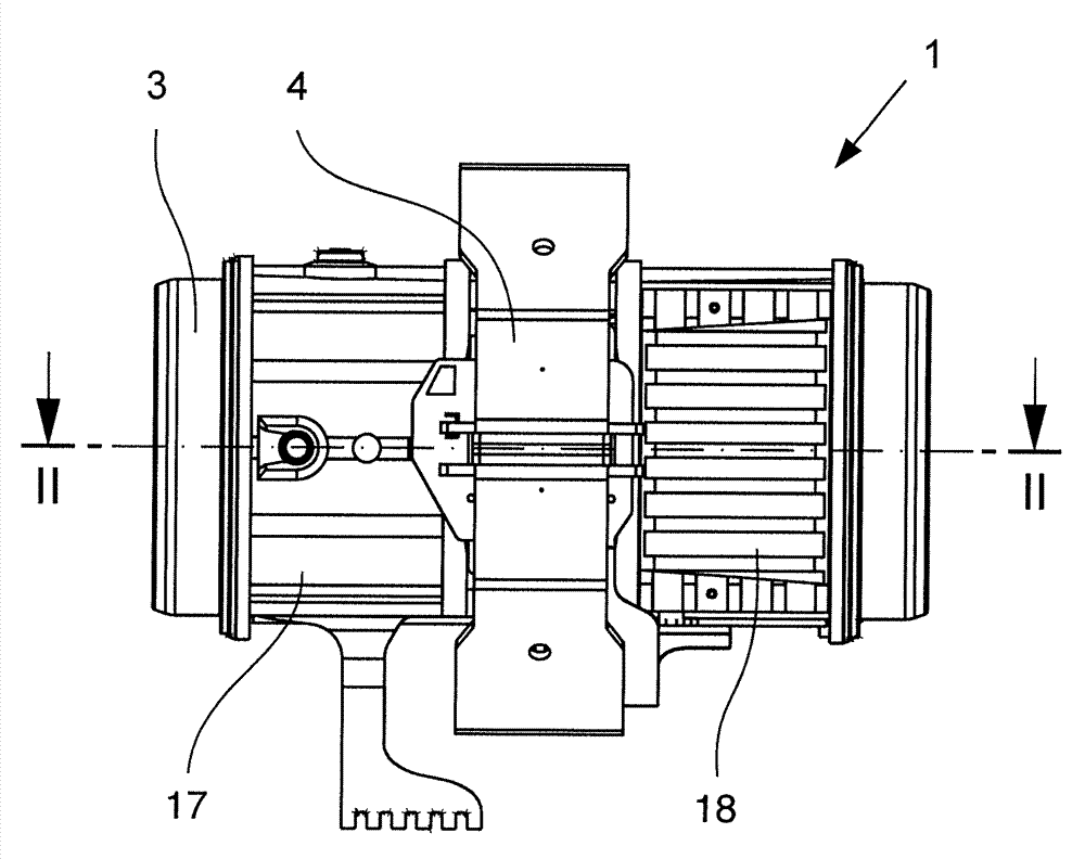
[0037] Figure 1 to Figure 3 A preferred exemplary embodiment of an electromagnetically inductive flowmeter 1 according to the invention for measuring the flow rate of a conductive medium 2 flowing in a measuring tube 3 is shown. For measuring the flow of the medium 2 , a magnetic field generator is provided which has two coils 4 which are externally mounted on the measuring tube 3 on opposite sides and which are supplied by a current generator (not shown here). A magnetic field generating device or coil 4 generates a magnetic field through which the measuring tube 3 runs approximately perpendicular to its longitudinal axis 5 . Furthermore, two measuring electrodes 6 , 7 are provided, which are galvanically connected to the medium 2 and which intercept the measuring voltage induced in the flowing medium 2 . In addition to the galvanic coupling of the measuring electrodes 6 , 7 provided here to the medium 2 , capacitive coupling is also possible in principle.

[0038] In addi...


PUM


Abstract

The invention relates to a magnetic-inductive flowmeter for measuring the flow rate of a flowing conductive medium with a measuring tube which consists of a nonconductive material, with a magnetic field generating apparatus for generating an especially changing magnetic field which permeates the measuring tube essentially perpendicular to the longitudinal axis of the measuring tube, with two measuring electrodes which are especially conductively coupled to the medium for tapping a measuring-circuit voltage which has been induced in the flowing medium and with a measuring device for detecting an empty tube, the measuring electrodes being located along a connecting line which runs perpendicular to the longitudinal axis of the measuring tube and perpendicular to the direction of the magnetic field. The measuring device for detecting an empty tube is made as an admittance measuring device which has a detector, a counter-electrode, an ac signal source and an evaluation unit, the detector having an electrode which is connected to the ac signal source so that the electrode can be loaded by an ac signal and furthermore the electric field extends from the electrode to a medium. The electrode of the detector and the counter-electrode are made planiform and are located essentially opposite one another on the outer surface of the measuring tube, the electrode of the detector being located above and the counter-electrode being located underneath the longitudinal axis of the measuring tube.

Description

technical field [0001] The invention relates to an electromagnetically inductive flowmeter for measuring the flow of a flowing, conductive medium, with a measuring tube consisting of a non-conductive material; for generating a longitudinal axis approximately perpendicular to the measuring tube A magnetic field generator for an in particular alternating magnetic field penetrating the measuring tube; two measuring electrodes, in particular galvanically coupled to the medium, for intercepting a measuring voltage induced in the flowing medium; and a measuring device for empty tube detection, wherein , the measuring electrodes are arranged along connecting lines extending perpendicular to the longitudinal axis of the measuring tube and perpendicular to the direction of the magnetic field. Background technique [0002] Electromagnetic-inductive flowmeters, the operating principle of which is based on the principle of electromagnetic induction (Faraday induction), have been known f...

Claims


Application Information

Patent Timeline
Patent Type & Authority Applications(China)
IPC IPC(8): G01F1/58
CPCG01F1/58G01F1/60G01F1/588
Inventor W.雷查特C.克雷塞R.克里伊森M.科伯S.里伊尔W.霍奇
Owner IMF ELECTRONIC GMBH
Why Eureka
Try Eureka