Parallel connection method and parallel connection device for multiple local discharge signals

A technology of discharge signal and partial discharge, applied in testing circuits, electrical components, testing dielectric strength, etc., can solve the problems of signal energy attenuation, signal loss, and the inability of switching circuits to achieve signal self-triggered closing and shut-off, to improve the The effect of safe operation of equipment and avoidance of loss

Active Publication Date: 2014-04-02
SHANGHAI JIAO TONG UNIV
6 Cites 5 Cited by

AI-Extracted Technical Summary

Problems solved by technology

[0005] The disadvantage of scheme A is that the circulator isolates the reverse signal by absorbing signal energy. For non-selective transmission signals in multiple transmission signals, that is, other UHF signals transmitted from parallel connection branches in the signal bus , it will produce a large amount of signal energy attenuation when passing through the signal ...

Abstract

The invention discloses a parallel connection method and a parallel connection device for multiple local discharge signals. The parallel connection method comprises the following steps: receiving signals input by multiple local discharge sensors, and preprocessing the local discharge sensors to obtain amplifying signals; isolating on the amplifying signals to enable the signals to be unidirectionally transmitted in a self-triggering manner, and finally, outputting all the isolated signals, wherein the delay transmission of ultrahigh-frequency local discharge signals is realized by adopting a surface acoustic wave delay line set. According to the parallel connection method and the parallel connection device disclosed by the invention, by amplifying and isolating the multiple signals, the signals can be unidirectionally transmitted in a self-triggering manner and isolated, further, the non-interfering parallel connection of the multiple local discharge signals is realized, and the signal loss during a signal transmission process is further avoided. Meanwhile, the local discharge detection signals connected in parallel are sent to a signal bus, and the multiple signals are monitored simultaneously by a data acquisition unit, and therefore, the goal that data acquisition is performed through the same set of data acquisition units is achieved, and the cost is reduced.

Application Domain

Testing using acoustic measurementsTransmission +1

Technology Topic

Ultrahigh frequencySelf triggering +6

Image

  • Parallel connection method and parallel connection device for multiple local discharge signals
  • Parallel connection method and parallel connection device for multiple local discharge signals
  • Parallel connection method and parallel connection device for multiple local discharge signals

Examples

  • Experimental program(2)

Example Embodiment

[0051] Example one:
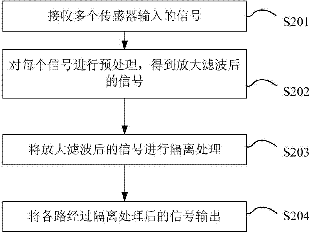
[0052] figure 2 This is a flowchart of a method for parallel connection of multiple partial discharge signals provided by an embodiment of the present invention.
[0053] Such as figure 2 As shown, the method includes the following steps:
[0054] Step S201: Receive signals input by multiple sensors.
[0055] The sensors include partial discharge UHF sensors, ultrasonic sensors, and high frequency current sensors, which respectively generate UHF sensing signals, ultrasonic signals, and high frequency current signals. That is, this step can be specifically: receiving multiple local UHF sensor inputs Ultra-high-frequency sensing signals from, ultrasonic sensing signals input by multiple ultrasonic sensors, and high-frequency current sensing signals input from multiple high-frequency current sensors.
[0056] Step S202: preprocessing each signal, including amplification and filtering, to obtain amplified and filtered signals. Among them, in the preprocessing of the partial discharge UHF signal, the frequency reduction process of detection is also required.
[0057] Step S203: Perform isolation processing on the amplified and filtered signal.
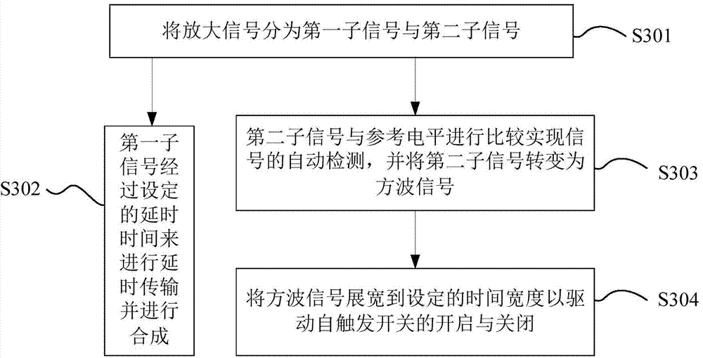
[0058] Further, in order to avoid mutual interference between multiple signals in the signal transmission process, the amplified and filtered signal is subjected to isolation processing, so that the signal can be self-triggered and unidirectional transmission. See the specific isolation process image 3 As shown, image 3 This is a flow chart for isolating an amplified signal provided by an embodiment of the present invention, and isolating the amplified and filtered signal includes the following steps:
[0059] Step S301: Divide the amplified signal into a first sub-signal and a second sub-signal.
[0060] Step S302: If the first sub-signal is a partial discharge UHF signal, the first sub-signal is delayed for transmission after a set delay time, and the first sub-signal after delayed transmission is divided into multiple frequency bands Signal group, after each group of signals are delayed, they are combined and amplified by a signal synthesizer; then output through the self-trigger switch, or then the signal output by the self-trigger switch is detected and processed;
[0061] Specifically, the delay time is greater than or equal to the sum of the self-triggered switch control circuit and the action time of the self-triggered switch. The delay time of the partial discharge UHF signal is realized by the surface acoustic wave delay line group, and the delayed transmission of the partial discharge is very high. The frequency signal frequency band is 400MHz~500MHz, 700MHz~800MHz, 1100MHz~1200MHz, and the delay time is 100ns. The surface acoustic wave delay line group, because of its frequency selection feature, can complete the filtering of the signal.
[0062] Step S303: The second sub-signal is compared with the reference level to realize automatic detection of the signal, and the second sub-signal is converted into a drive signal of the switch, for example, the drive signal of the switch may be a square wave.
[0063] Specifically, the reference level is an adjustable reference level that has been set, which can be adjusted according to specific conditions when setting. The second sub-signal is compared with the reference level to realize automatic signal detection, level conversion, and transition. It is a drive signal of a switch with a constant voltage and a pulse width consistent with the input signal.
[0064] Step S304: Extend the drive signal of the switch to a set time width to drive the self-triggered switch to turn on and off.
[0065] Step S204: Output the signals of each channel after isolation processing.
[0066] At this time, the partial discharge UHF signal has passed a certain time delay, and it is transmitted to the self-trigger switch just after the second sub-signal starts the switch, thus ensuring that the partial discharge UHF signal completely passes through the self-trigger switch, realizing the signal The self-triggered one-way transmission, which realizes the interference-free parallel connection of multiple partial discharge UHF signals, avoids the loss in the signal transmission process.
[0067] It can be seen from the above technical solutions that the method for parallel connection of multiple partial discharge signals provided by the embodiment of the present invention receives signals input from multiple sensors and performs preprocessing such as amplifying each signal to obtain an amplified signal. The amplified signal is subjected to isolation processing, so that the signal can be self-triggered and one-way transmission, and finally the signals after the isolation processing of each path are completely output. Compared with the prior art, the present invention amplifies and isolates multi-path partial discharge signals, so that the signals can be self-triggered and unidirectional transmission and isolation, thereby realizing multi-path partial discharge The interference-free parallel connection of signals further avoids signal loss during signal transmission.
[0068] At the same time, the parallel connection method of multiple partial discharge signals, due to the parallel connection of partial discharge signals The detection signals are all transmitted to the signal bus, and a data acquisition device can monitor multiple signals at the same time, thus realizing data acquisition through the same set of data acquisition device, realizing synchronous online monitoring of multiple power equipment at a lower cost, and timely The purpose of finding insulation defects in power equipment and improving equipment operation safety.

Example Embodiment

[0069] Embodiment two:
[0070] On the basis of the first embodiment, the embodiment of the present invention also provides a parallel connection device for multiple partial discharge signals, such as Figure 4 As shown, it is a schematic diagram of a parallel connection device for multiple partial discharge signals provided by an embodiment of the present invention.
[0071] The multiple partial discharge signal parallel connection device includes the following sub-devices:
[0072] The signal input interface 401 is used to receive signals input by multiple sensors.
[0073] The sensors include partial discharge UHF sensors, ultrasonic sensors, and high frequency current sensors, which respectively receive partial discharge UHF sensing signals, ultrasonic signals, and high frequency current signals. That is, the signal input interface 401 is specifically used to receive multiple partial discharge characteristics. Partial discharge ultra-high frequency sensing signals input by high-frequency sensors, ultrasonic sensing signals input from multiple ultrasonic sensors, and high-frequency current sensing signals input from multiple high-frequency current sensors.
[0074] The signal input interface 401 preferably includes a radio frequency signal interface, connected to a partial discharge UHF sensor, and the frequency influence range is greater than 300 MHz to less than 1.5 GHz.
[0075] The signal amplifying circuit 402 is used for preprocessing each of the signals, including amplifying, filtering, etc., to obtain amplified and filtered signals. The signal amplifying circuit 402 is preferably a low-noise amplifier, with an amplification gain greater than or equal to 20 dB, and a frequency response range from greater than 300 MHz to less than 3 GHz.
[0076] The signal isolation circuit 403 is used for isolating the amplified and filtered signal, so that the signal can be self-triggered and unidirectional transmission. Among them, for the partial discharge UHF signal, after the signal passes through the self-triggering switch in the signal isolation circuit 403, it can be detected by a wave detector.
[0077] In order to avoid mutual interference between multiple signals during signal transmission, the amplified and filtered signal is isolated by the signal isolation circuit 403. Such as Figure 5 As shown, Figure 5 It is a schematic diagram of a signal isolation circuit provided by an embodiment of the present invention. The signal isolation circuit 403 includes:
[0078] The signal separation circuit 501 is used to divide the amplified signal into a first sub-signal and a second sub-signal;
[0079] The partial discharge UHF signal delay circuit 502 is used for delaying transmission of the first sub signal after a set delay time when the first sub signal is a partial discharge UHF signal.
[0080] The emitter follower circuit 508 is used to delay the first sub-signal and output it through a self-triggering switch when the first sub-signal is a high-frequency current signal or an ultrasonic signal. In the modified example, the emitter follower circuit 508 can be omitted, that is, the high-frequency current signal and the ultrasonic signal are directly output through the self-trigger switch without delay.
[0081] Specifically, the partial discharge UHF signal delay circuit 502 is a surface acoustic wave delay line group, and the delayed transmission partial discharge UHF signal frequency bands are 400MHz~500MHz, 700MHz~800MHz, 1100MHz~1200MHz, and the delay time is 100ns. The delay time of the partial discharge UHF signal delay circuit 502 is greater than or equal to the sum of the self-trigger switch control circuit and the action time of the self-trigger switch.
[0082] The signal synthesis circuit 507 is configured to combine and amplify the multiple frequency band signals divided into the first sub-signal after delayed transmission by the partial discharge UHF signal delay circuit, and then transmit to the self-trigger switch 506 for output; In a preferred example, the signal output from the trigger switch 506 is subjected to detection processing.
[0083] The reference voltage circuit 503 is used to provide a reference level.
[0084] Specifically, the reference level is a set adjustable reference level, which is provided by the reference voltage circuit 503. When the reference voltage circuit 503 sets the reference level, it can be adjusted according to the specific situation, and adjusted to produce the required reference level. until.
[0085] The high-speed comparison circuit 504 is configured to compare the second sub-signal with the reference level provided by the reference voltage circuit 503 to realize automatic detection of the signal, and convert the second sub-signal into a switch drive signal, such as a square wave signal.
[0086] Specifically, the second sub-signal is compared with the reference level to realize automatic detection of the signal, and the level conversion is performed to convert it into a drive signal of a switch with a constant voltage and a pulse width consistent with the input signal.
[0087] The monostable trigger circuit 505 is used to expand the drive signal of the switch to a set time width to drive the self-trigger switch 506 to turn on and off.
[0088] Among them, the monostable trigger circuit 505 is a monostable trigger circuit based on a 555 timer, and the transient steady state time is less than 1 us. The action time of the self-triggering switch 506 is less than 10 ns.
[0089] The signal output interface 404 is used for outputting the signals of each channel after isolation processing.
[0090] The signal output interface 404 may preferably correspond to a radio frequency signal interface, and its frequency response range is greater than 300 MHz to less than 1.5 GHz.
[0091] At this time, the partial discharge UHF signal passes through a certain time delay of the partial discharge UHF signal delay circuit 502, and it is transmitted to the self-triggered switch just after the second sub-signal starts the switch, thereby ensuring the integrity of the UHF signal Through the self-triggering switch, the self-triggering one-way transmission of the signal is realized, and the interference-free parallel connection of multiple partial discharge UHF signals is realized, and the loss in the signal transmission process is avoided.
[0092] It can be seen from the above technical solutions that the multi-channel signal parallel connection device provided by the embodiment of the present invention receives signals input from multiple sensors, and performs preprocessing such as amplifying each of the signals to obtain an amplified signal. The signal is isolated and processed so that the signal can be self-triggered and one-way transmission, and finally the signals after isolation processing of each channel are completely output. Compared with the prior art, the present invention amplifies and isolates multiple signals so that the signals can be self-triggered one-way transmission and isolation, thereby realizing interference-free parallel connection of multiple partial discharge signals, and further avoiding the signal transmission process Loss of medium signal.
[0093] At the same time, the multi-channel partial discharge signal parallel connection device, because the partial discharge detection signals connected in parallel are all transmitted to the signal bus, a data acquisition device can monitor multiple signals at the same time, thereby realizing data acquisition through the same data acquisition device , Realize the simultaneous online monitoring of multiple power equipment at a low cost, find the insulation defects of the power equipment in time, and improve the safety of equipment operation.

PUM

no PUM

Description & Claims & Application Information

We can also present the details of the Description, Claims and Application information to help users get a comprehensive understanding of the technical details of the patent, such as background art, summary of invention, brief description of drawings, description of embodiments, and other original content. On the other hand, users can also determine the specific scope of protection of the technology through the list of claims; as well as understand the changes in the life cycle of the technology with the presentation of the patent timeline. Login to view more.

Similar technology patents

Classification and recommendation of technical efficacy words

Why Eureka
Try Eureka