Relay system

A relay and battery technology, applied in the direction of electrical program control, sequence/logic controller program control, etc., can solve the problems of resource occupation, easy burning, inconvenience, etc.

Active Publication Date: 2014-04-02
SHANGHAI JINGDUN TECH ECONOMIC INFORMATION
View PDF5 Cites 6 Cited by
  • Summary
  • Abstract
  • Description
  • Claims
  • Application Information

AI Technical Summary

Problems solved by technology

However, in the process of controlling high voltage and strong current, etc., the relay is in the working state, thus consuming energy; moreover, two signal controls are required, one signal control is turned on, and the other signal control is turned off, which is very inconvenient and takes up resource
Furthermore, various relays appearing on the market have many defects such as energy consumption, easy burning, and misoperation.

Method used


Image

  • Relay system
  • Relay system
  • Relay system

Examples


Embodiment Construction

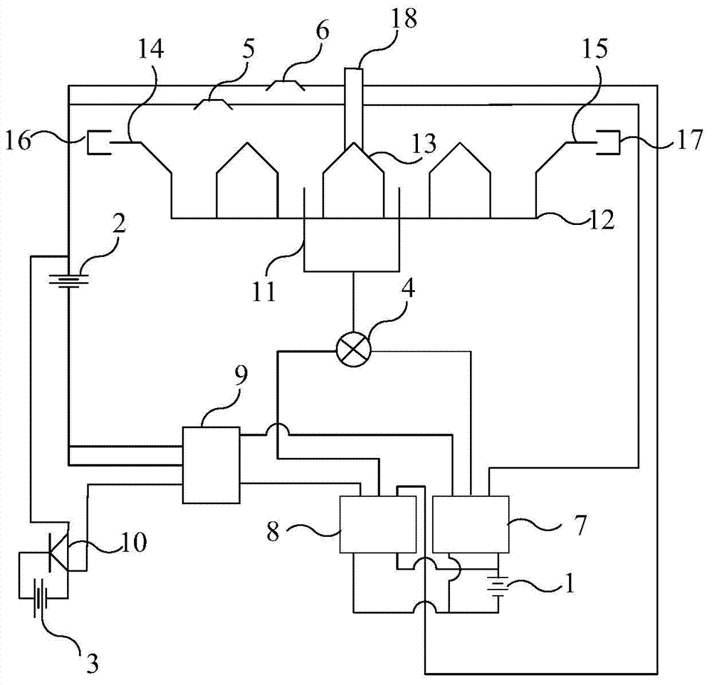
[0023] like figure 1 Shown is a schematic structural diagram of a preferred embodiment of the relay system of the present invention.

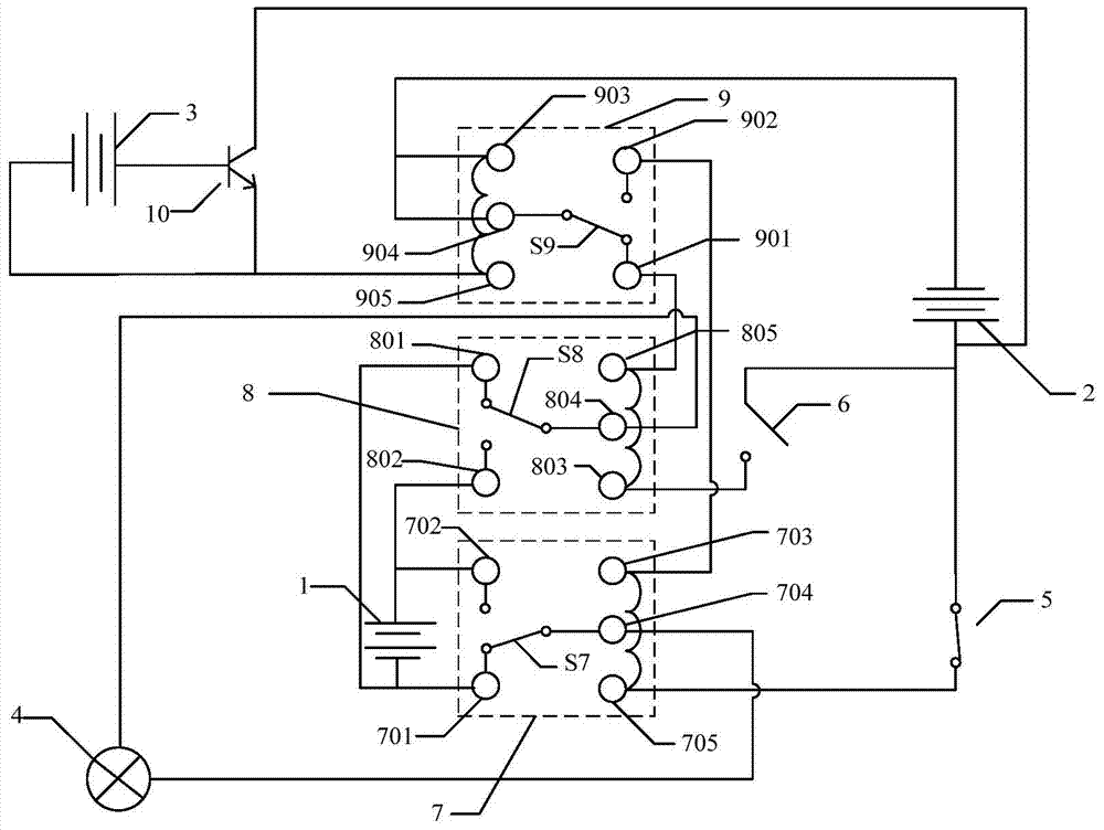
[0024] The relay system includes a first five-pin relay 7, a second five-pin relay 8, a motor 4, a first battery 1, a second battery 2, a first switch 5, a second switch 6, a third five-pin relay 9 and multiple A ribbed rack 12 with ribbed teeth 13. .

[0025] The normally open terminal 702 of the first five-pin relay 7 is electrically connected to the normally open terminal 802 of the second five-pin relay 8 . The normally closed terminal 701 of the first five-pin relay 7 is electrically connected to the normally closed terminal 801 of the second five-pin relay 8 . One terminal of the motor 4 is electrically connected to the common terminal 704 of the first five-pin relay 7 , and the other terminal of the motor 4 is electrically connected to the common terminal 804 of the second five-pin relay 8 . One pole (positive pole in this embodiment...


PUM


Abstract

The invention discloses a relay system, which comprises a first five-pin relay, a second five-pin relay, a motor, a first switch, a second switch and a ridge rack, wherein a normally open terminal of the first five-pin relay is electrically connected with a normally open terminal of the second five-pin relay, a normally closed terminal of the first five-pin relay is electrically connected with a normally closed terminal of the second five-pin relay, a wiring terminal of the motor is electrically connected with a common terminal of the first five-pin relay, the other wiring terminal of the motor is electrically connected with the common terminal of the second five-pin relay, the ridge rack is provided with a plurality of ridge teeth, a first wiring terminal of the first switch is electrically connected with a second voltage applying terminal of the first five-pin relay, a first wiring terminal of the second switch is electrically connected with a first voltage applying terminal of the second five-pin relay, and the motor is used for driving the ridge rack to move so as to open and close the first switch and the second switch.

Description

technical field [0001] The invention relates to the field of relays, in particular to a relay system. Background technique [0002] The relay is an electrical control device, which is an electrical appliance that causes the controlled quantity to undergo a predetermined step change in the electrical output circuit when the change of the input quantity meets the specified requirements. It has an interactive relationship between the control system and the controlled system. Usually used in automatic control circuits, it is actually an "automatic switch" that uses a small current to control the operation of a large current. Therefore, it plays the role of automatic adjustment, safety protection, and conversion circuit in the circuit. [0003] Chinese invention patent CN102064748A discloses a method of integrating relays and a remote switch knife. By connecting two relays and motors to form an integrated relay system, it can be combined with digital modules or microcomputers t...

Claims


Application Information

Patent Timeline
Patent Type & Authority Applications(China)
IPC IPC(8): G05B19/04
Inventor 罗元德王光树
Owner SHANGHAI JINGDUN TECH ECONOMIC INFORMATION
Why Eureka
Try Eureka