
Improved photoelectric keyboard device for playing

A keyboard device and photoelectric technology, which is applied in the field of musical instruments, can solve the problems of easy aging and wear of conductive adhesive, difficulty in obtaining materials, and poor playing feel, and achieve the effect of improving touch feeling, easy access, and novel design

Active Publication Date: 2014-04-02
马季平
View PDF5 Cites 4 Cited by
  • Summary
  • Abstract
  • Description
  • Claims
  • Application Information

AI Technical Summary

Problems solved by technology

[0007] The purpose of the present invention is to improve the disadvantages of the contact-type conductive glue method in the prior art that the playing feel is not good, the conductive glue is also prone to aging, wear and elastic fatigue, and the photoelectric device of the musical instrument dynamic keyboard adopts infrared light dual-control photosensitive receiving tubes. High, difficult to obtain materials, provide a simple structure, low cost, good reliability and consistency, improved playing feel, easy access to materials, easy assembly and improved photoelectric keyboard device for playing

Method used


Image

  • Improved photoelectric keyboard device for playing
  • Improved photoelectric keyboard device for playing
  • Improved photoelectric keyboard device for playing

Examples


Embodiment 1

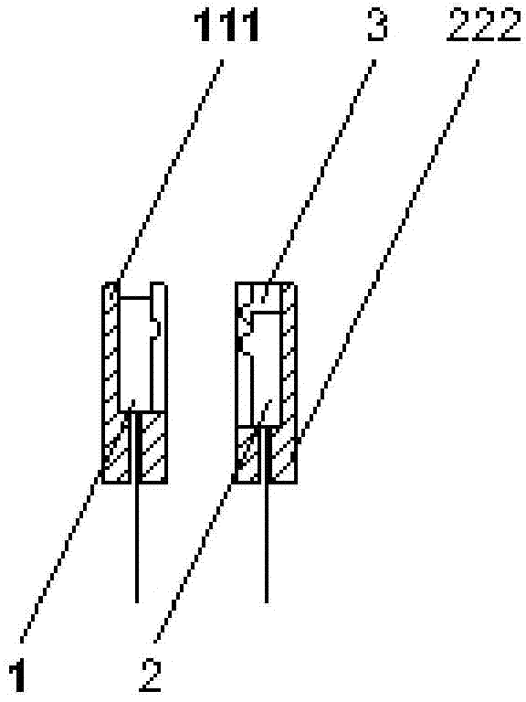
[0036]The technical scheme adopted by the present invention is as follows: transform the structure of the traditional lever-type mechanical piano keyboard with alternately front and rear black keys and white key pins, and displace the position of the black key pins in the mid-range of the keyboard and the pin holes of the black keys so that the side view When using the keyboard, the middle pins of the black keys and white keys are at the same projection position in the middle; place an L-shaped aging-resistant elastic silicone strip with a cross-sectional thickness of about 3 to 4 mm on the side of the middle of the keyboard facing the front, and the cross-sectional length of the other side of the silicone strip is about It is 10-12 mm, close to the bottom of the keys. When playing the keys, the bottom of the keys presses the silicone strip. After adding the elastic rubber strip, the fulcrum of the keys is moved forward when playing, and the weight is reduced. The middle of the...

Embodiment 2

[0044] Figure 7 It is the structural diagram a of the first kind of photoelectric keyboard device in the present invention, and the corresponding positions of the right, middle and left parts below the keys 14 are respectively provided with a keyboard front shelf 5, a middle shelf 8 and a rear shelf 13 to form a keyboard frame. There are white key positioning pins 6 and black key positioning pins 7, black and white key positioning pins are provided with black and white keys, mid-range round pins 10 are provided on the mid-range 8, which are used for positioning the fulcrum of the 14 keys, and a weight is provided on the upper left part of the keys 14 17. The side of the mid-range 8 facing the front is provided with an L-shaped silicone elastic strip with a cross-sectional thickness of about 3 to 4 mm. The elastic strip 9 is connected to the side of the mid-range 8 by bridge-shaped air gun nails. The elastic strip 9 traverses the key 14 Below, its other side is slightly shorte...

Embodiment 3

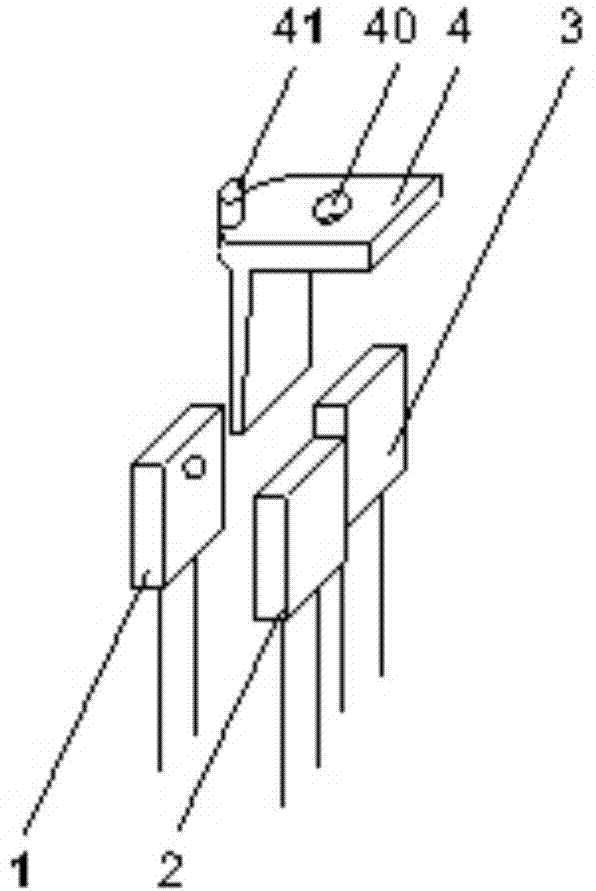
[0047] In the circuit design of electronic musical instruments, the keyboard is usually decomposed into a matrix scanning circuit composed of several horizontal rows and vertical columns. As the two ends of the scanning signal input and reading, all the keys correspond to the cross nodes in the rows and columns. The 88-key electric piano keyboard of the present invention is defined as a matrix scanning circuit with a relationship of 8×11 rows and columns, that is, 8 scanning signal input lines and 22 scanning signal output (reading) lines, of which 11 output lines are used for reading In the infrared optocoupler unit, the scanning signal output by the infrared receiving diode that first turns on or off the switching action, and the other 11 output lines are used to read the scanning signal output by the infrared receiving diode that subsequently turns on or off the switching action in the infrared optocoupler unit; By reading the scanning signals output by two infrared receivin...


PUM

PropertyMeasurementUnit
Thicknessaaaaaaaaaa

Abstract

The invention relates to the field of musical instruments, in particular to an improved photoelectric keyboard device for playing. The improved photoelectric keyboard device comprises keys, front blocks, front block wool rings, black and white keys, positioning pins, middle blocks, middle wool rings, middle block pins, back blocks, back block wool bars, key pressing stop levers, balancing weights, light-blocking sheets, limiting nails, buffering felts, printed circuit boards, a power supply, infrared emitting diodes, infrared receiving diodes and a plastic shell, wherein a keyboard consists of the keys, the front blocks, the black and white keys, the positioning pins, the middle blocks, middle circular pins, the key pressing stop levers, brackets, the back blocks, the balancing weights and the circuit boards; one side, which is opposite to each front block, of the right side of the keyboard middle blocks is provided with an elastic rubber bar which is approximately L-shaped; the shorter edge of the upper part of each L shape is close to the bottom surface of the central position of each key; the light-blocking sheets are arranged on the bottom surfaces of the left parts of the keys close to the back blocks. Compared with the prior art, the improved photoelectric keyboard device has the advantages that one infrared emitting diode and two infrared receiving diodes construct a photoelectric coupling circuit, so that balanced strength reaction, low cost and easiness is assembling are realized.

Description

[technical field] [0001] The invention relates to the field of musical instruments, in particular to an improved photoelectric keyboard device for playing. [Background technique] [0002] The traditional mechanical piano keyboard is a lever-type keyboard, which is widely used because of its simple structure, easy maintenance, and suitable playing touch. With the advancement of science and technology, the electronic organ was born and gradually developed, and the functions of the electronic organ are also becoming more and more perfect. [0003] Due to the dynamic characteristics of piano keys, most electronic pianos and electronic pianos now simulate the dynamic effect of traditional pianos. The principle is: to detect the time difference between two constant points in the movement of the keys, the acceleration and dynamics can be obtained, and then the sound source can be controlled. Volume intensity effect. Most of the force detection circuits commonly used for piano key...

Claims


Application Information

Patent Timeline
IPC IPC(8): G10H1/34
Inventor 马季平
Owner 马季平
Learn More