

Plug-in type exhaust fan for switchgear
A switchgear and exhaust fan technology, applied in the direction of cooling/ventilation of substations/switchgears, can solve problems affecting the reliability of equipment operation, and achieve the effect of ensuring safe operation and power supply reliability
Inactive Publication Date: 2014-04-02
STATE GRID CORP OF CHINA +1
View PDF4 Cites 5 Cited by
- Summary
- Abstract
- Description
- Claims
- Application Information
AI Technical Summary
Problems solved by technology
At present, some manufacturers in the market have applied exhaust fans to the design of the top of the switchgear, and opened installation holes on the top of the switchgear, and fixed the exhaust fans in the installation holes. Equipment operation reliability
Method used
View moreImage
Smart ImageViewing Examples

Examples
Embodiment Construction
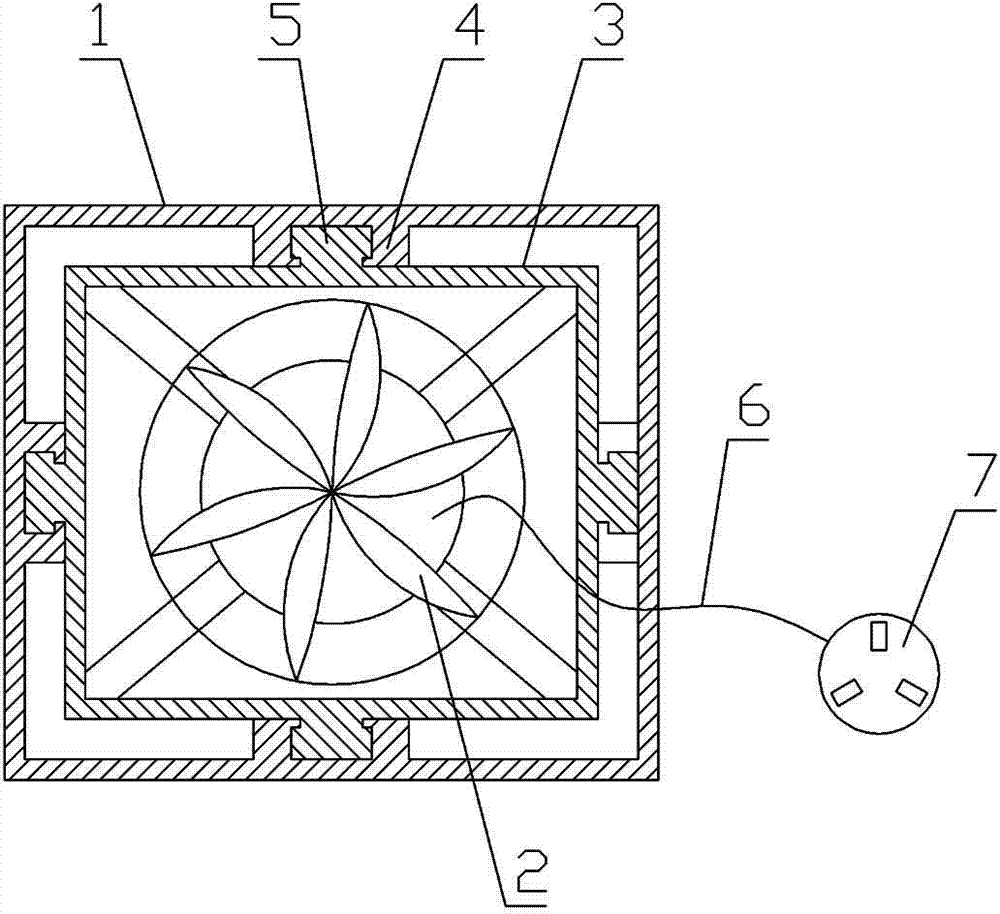
[0008] see figure 1 , an exhaust fan for a pluggable switch cabinet, its structure includes an outer fixed frame 1, a fan 2, and an inner fixed frame 3, the inner side of the outer fixed frame 1 is provided with a guide rail 4, and the fan 2 is fixed on the inner fixed frame 3 Inside, the outer side of the inner fixing frame 3 is provided with a slider 5 matching with the guide rail 4 , and the power lead wire 6 of the driving motor of the fan 2 is connected with a power plug 7 . When in use, the outer fixing frame 1 is installed in the existing installation hole on the top of the switch cabinet.
Login to View More PUM
 Abstract
The invention belongs to ancillary fittings of current supply equipment, in particular to a plug-in type exhaust fan for a switchgear. The exhaust fan mainly comprises an external fixed frame, a fan and an internal fixed frame, wherein the inside of the external fixed frame is provided with a guide rail; the fan is fixed in the internal fixed frame; the external side of the internal fixed frame is provided with a cam block matched with the guide rail; a power lead of a drive motor of the fan is connected with a power plug. According to the invention, the installation mode of the exhaust fan of the switchgear is reconsidered, the power plug of the exhaust fan is provided, the installation mode that the guide rail is demountable is adopted, the purpose of replacing the exhaust fan quickly on the premise that the operation of the switchgear is not influenced is realized, and the safe operation and the reliable power supply of the switchgear can be effectively guaranteed.
Description
technical field [0001] The invention belongs to auxiliary accessories of power supply equipment, in particular to an exhaust fan for a plug-in switch cabinet. Background technique [0002] In the prior art, the switchgear is designed as a closed space or partially equipped with a ventilation grid structure. During use, the air in the cabinet is not circulated and humid, and condensation is prone to occur when the temperature changes, resulting in short-circuit damage to the equipment in the switchgear. , especially for areas with high humidity, such problems are more prominent. According to relevant statistics, among the causes of switchgear equipment failures, the failures caused by air condensation and short circuit account for more than 30%. Especially the KYN type small car cabinet. In order to pursue the goal of compact structure and small space occupation, this type of switchgear often adopts methods such as adding insulating sleeves or insulating partitions to short...
Claims
Login to View More Application Information
Patent Timeline
 Patent Type & AuthorityApplications(China)
IPC IPC(8): H02B1/56
Inventor魏韬韩爱芝闫然峰史意更蔡坤
OwnerSTATE GRID CORP OF CHINA