Portable scanner and scanning route calculation method thereof

A technology of path calculation and calculation method, applied in the field of scanning, can solve the problems of large scanning error, complex structure and wear of photoelectric scanner, and achieve the effect of compact structure

Active Publication Date: 2014-04-02
MINGSHUO COMP (SUZHOU) CO LTD +1
View PDF4 Cites 5 Cited by
  • Summary
  • Abstract
  • Description
  • Claims
  • Application Information

AI Technical Summary

Problems solved by technology

However, whether it is infrared, variable speed gear or motor control technology, a gearbox is required, so the structure of the mechanical scanner is often complex and requires high precision.
In addition, the internal structural parts of the mechanical scanner are also prone to wear and tear during use, resulting in large scanning errors and troublesome replacement, which reduces the stability and performance of the mechanical scanner
In addition, if the mechanical scanner shakes during scanning, the position track scanned by the mechanical scanner will be lost, which will cause the scanned image to be distorted
[0003] On the other hand, photoelectric scanners mainly use light emitting diodes (Light Emitting Diode, LED) as light sources, so they cannot scan on transparent objects such as glass and film.
In addition, since the photoelectric scanner is usually only equipped with a single photoelectric sensor, it can only detect simple linear displacement. That is to say, when the user needs to perform rotational scanning, the photoelectric scanner will not be able to scan smoothly. It may even be impossible to scan
In addition, the photoelectric scanner also has a combination configuration of multiple photoelectric sensors and scanning modules, but this combination configuration will lead to a complex structure of the photoelectric scanner. In addition, the photoelectric scanner using this combination configuration cannot be paused or stopped during the scanning process. Get out of the scanned object, otherwise you have to rescan

Method used


Image

  • Portable scanner and scanning route calculation method thereof
  • Portable scanner and scanning route calculation method thereof
  • Portable scanner and scanning route calculation method thereof

Examples


Embodiment Construction

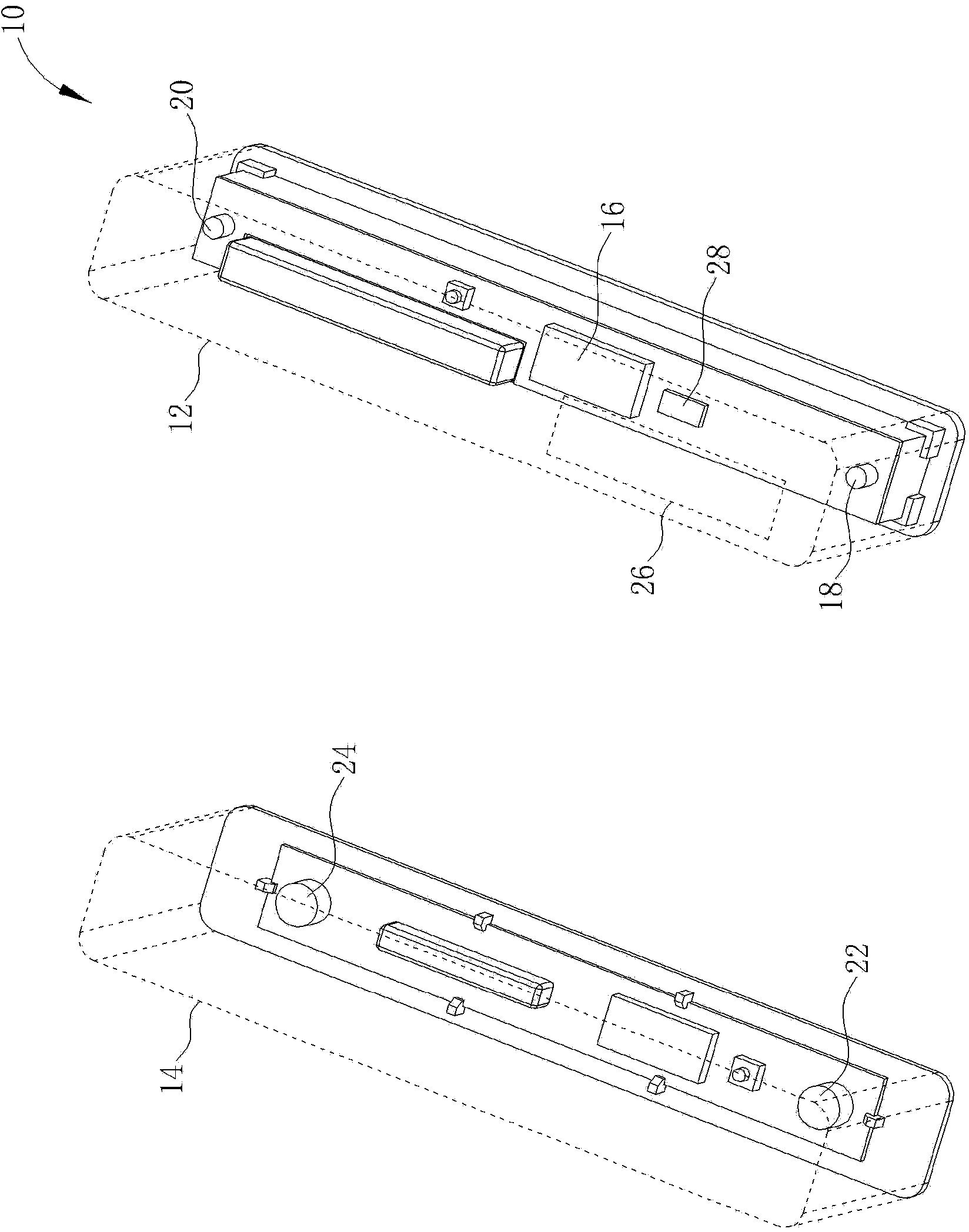
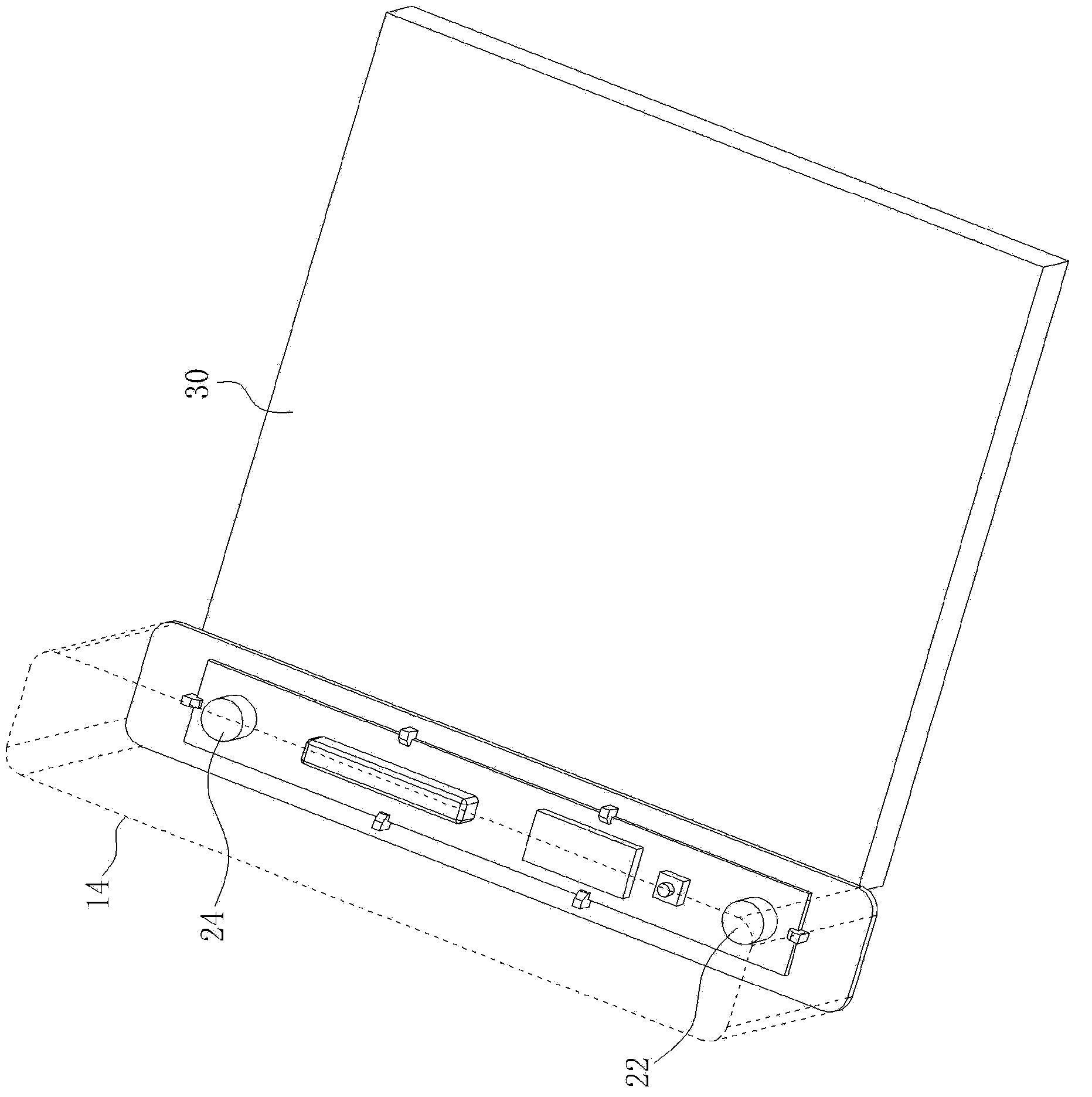
[0036] Please refer to figure 1 , which is a schematic diagram of a portable scanner 10 proposed according to a preferred embodiment of the present invention. The portable scanner 10 is used to scan objects to be scanned (such as books, engineering drawings, etc.), such as figure 1 As shown, the portable scanner 10 includes a scanning module 12, a reference module 14 and a path calculation component 16. In order to clearly show the internal design of the scanning module 12 and the reference module 14, the shells of the scanning module 12 and the reference module 14 are figure 1 It is simply indicated by a dotted line. The scanning module 12 can move relative to the object to be scanned to scan the object to be scanned, the scanning module 12 includes a first positioning unit 18 and a second positioning unit 20, and the reference module 14 is used to be arranged on the edge of the object to be scanned and includes A first reference unit 22 and a second reference unit 24. In th...


PUM


Abstract

The invention discloses a portable scanner and a scanning route calculation method thereof. The portable scanner comprises a scanning module, a reference module and a route calculation component, wherein the scanning module can move relative to an object to be scanned so as to scan the object to be scanned; the scanning module comprises a first positioning unit and a second positioning unit; the reference module is arranged on the edge of the object to be scanned and comprises a first reference unit and a second reference unit; the route calculation component is electrically connected with the first reference unit and the second reference unit; when the scanning module scans the object to be scanned, the reference module and the object to be scanned are kept relatively rest, the route calculation component calculates a movement route of the scanning module according to the position information among the first positioning unit, the first reference unit and the second reference unit and the position information among the second positioning unit, the first reference unit and the second reference unit.

Description

technical field [0001] The invention relates to a scanning technology, in particular to a portable scanner and a scanning path calculation method thereof. Background technique [0002] Generally speaking, the synchronous control mechanism of the hand-held scanner mainly has two designs: mechanical type and photoelectric type. At present, the hand-held scanners on the market are mainly of the mechanical roller type. Synchronous motors are generally used as the transmission mechanism to scan documents synchronously by controlling the rotation of the motor. In addition, infrared rays and transmission gears are also used to detect the displacement distance and then control the scanning. the design of. However, whether it is infrared, transmission gear or motor control technology, a gearbox is required, so the structure of the mechanical scanner is often complex and requires high precision. In addition, the internal structural parts of the mechanical scanner are also prone to w...

Claims


Application Information

Patent Timeline
IPC IPC(8): H04N1/04
Inventor 蔡琦飞裘耀华
Owner MINGSHUO COMP (SUZHOU) CO LTD
Why Eureka
Try Eureka