Electrified curing machine

A curing machine and rack technology, which is applied to ohmic resistance heating parts and heating elements, can solve the problems of poor heat dissipation, unsafe operation, and inconvenient removal, and achieves good heat dissipation effect, safe operation, and easy removal. Effect

Inactive Publication Date: 2014-04-02
盐城市北蒋电力机械厂
View PDF0 Cites 15 Cited by
  • Summary
  • Abstract
  • Description
  • Claims
  • Application Information

AI Technical Summary

Problems solved by technology

The heat dissipation support base plate of the existing energized curing machine is a flat plate, and the heat dissipation effect is

Method used


Image

  • Electrified curing machine
  • Electrified curing machine

Examples


Embodiment Construction

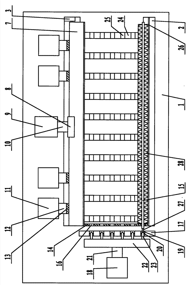
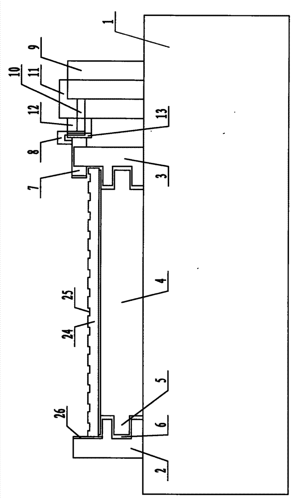
[0012] The specific content of the present invention will be described in detail below in conjunction with the accompanying drawings and specific embodiments.

[0013] Such as figure 1 , figure 2 As shown, the power-on curing machine includes: a frame 1, a left support block 2 and a right support block 3 are arranged on the frame 1, and several intermediate support blocks are arranged between the left support block 2 and the right support block 3. The support block 4 is provided with a slide block 5 on both sides of the middle support block 4, and a chute 6 cooperating with the slide block 5 is provided on the inner side of the lower end of the left support block 2 and the right support block 3. The upper end of the right supporting block 3 is provided with a sliding platen 7, the middle part of the sliding platen 7 is connected with the piston rod 10 of the positioning cylinder 9 through the connecting block 8, and the positioning cylinder 9 is arranged on the frame 1, The...


PUM


Abstract

The invention discloses an electrified curing machine which is convenient to operate. The curing machine comprises a frame, wherein the frame is provided with a left support block and a right support block, a plurality of middle support blocks are arranged between the left support block and the right support block, and a sliding clamp is arranged at the upper end of the right support block; the middle part of the sliding clamp is connected with the piston rod of a locating cylinder by a connecting block, the locating cylinder is arranged on the frame, and a locating plate is arranged on the frame between one ends of the left support block and the right support block; the locating plate is uniformly provided with a plurality of locating slots mutually matched with heat conduction pipes on a PTC (Positive Temperature Coefficient) heater, the frame at one side of the locating plate is provided with an electrode post fixing plate and a cylinder, and a plurality of mounting slots matched with the locating slots are uniformly arranged on the electrode post fixing plate; electrode posts are respectively arranged at the two sides of the mounting slots, a push plate is connected on the piston rod of the cylinder, and a plurality of connecting conductive posts mutually matched with the mounting slots are uniformly arranged on the push plate.

Description

technical field [0001] The invention relates to a curing device for a PTC heater, in particular to an electrified curing machine. Background technique [0002] PTC heater is a common heating device, mainly used in heating equipment, air conditioners, water heaters and other products. The structure of the PTC heater mainly includes: a heat pipe, a heat pipe of the PTC heater arranged in the heat pipe, and heat dissipation strips arranged on both sides of the heat pipe. In the production process of the PTC heater, it is necessary to use an energized curing machine to assemble the heat pipe and the cooling strips arranged on both sides of the heat pipe. The heat dissipation support base plate of the existing energized curing machine is a flat plate, and the heat dissipation effect is not good. After the workpiece is assembled, it is inconvenient to take out due to the high temperature, and the operation is unsafe. Contents of the invention [0003] The technical problem to ...

Claims


Application Information

Patent Timeline
IPC IPC(8): H05B3/06
Inventor 程卫国
Owner 盐城市北蒋电力机械厂
Why Eureka
Try Eureka