Pinch roll equipment

A pinch roll and equipment technology, applied in metal processing equipment, rolling force/roll gap control, metal rolling, etc., can solve the problems of low service life cycle, high operation and maintenance costs of servo valves, etc.

Active Publication Date: 2017-02-15
DANIELI & C OFF MEC SPA
View PDF10 Cites 0 Cited by
  • Summary
  • Abstract
  • Description
  • Claims
  • Application Information

AI Technical Summary

Problems solved by technology

[0008] - High operating and maintenance costs due to the generally low service life cycle of servo valves

Method used


Image

  • Pinch roll equipment
  • Pinch roll equipment
  • Pinch roll equipment

Examples


Embodiment Construction

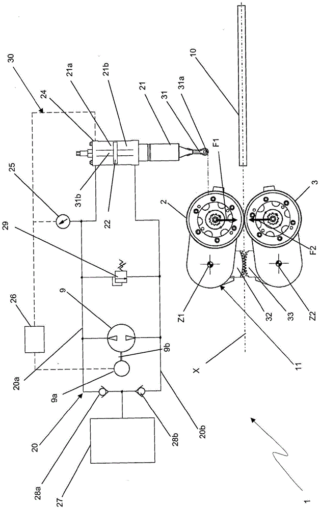
[0044] refer to Figure 1-3 , generally indicated by reference numeral 1 is a pinch roll arrangement for rolled metallurgical products of circular cross-section.

[0045] In general, pinch roll apparatus provided in accordance with the present invention may be suitably configured to grip any rolled metallurgical product, such as a flat cross-section rolled product.

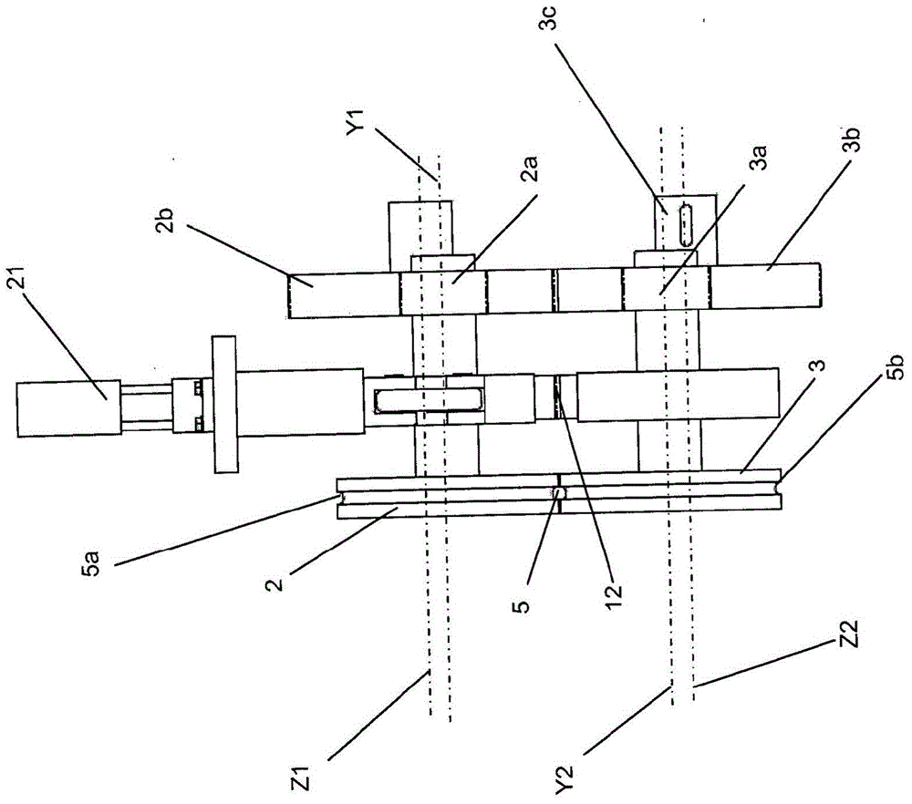
[0046]The apparatus 1 comprises a first pinch roll 2 and a second pinch roll 3 identical to the first roll 3 between which a generally circular passage gap for a rod wire 10 is defined 5. The gap 5 defines a passage axis X coaxial with the gap 5 , with which the rod wire 10 is operatively aligned when passing through the passage gap 5 .

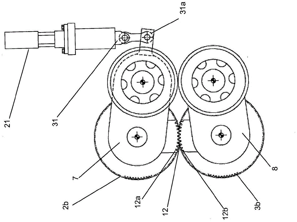
[0047] The first roller 2 and the second roller 3 can rotate around the first rotation axis Y1 and the second rotation axis Y2, respectively, to pull the rod wire 10 through the channel gap 5 by friction. The axes of rotation Y1 , Y2 are parallel to each other and at the same ...


PUM


Abstract

A pinch roll apparatus (1) for rolled metallurgical products, comprising: - first and second pinch rolls (2, 3) defining a channel gap (5) therebetween, a first The roll and the second roll (2, 3) are respectively rotatable about a first and a second axis of rotation (Y1, Y2) to pull the rolled metallurgical product (10) through the gap (5), ‑hydraulic Actuators (21, 41) comprising hydraulic actuators (21, 42, 43) connected to the first roller (2) and / or the second roller (3) so that the first roller and the second roller ( 2, 3) reciprocating approach or separation in order to respectively reduce or increase the width of the channel gap (5), -pressure sensor (25) in the hydraulic circuit (20), -position sensor in the actuator (21) (24), - Reversible pump (9) in the hydraulic circuit (20, 41) connected to the actuator (21, 42, 43) for sliding movement connected to the first roller (2) and / or the second Piston (22) for roller (3).

Description

technical field [0001] The present invention relates to a pinch roll device for rolled metallurgical products. Background technique [0002] In the technical field of wire processing for semi-formed metallurgical products, such as wire rods, it is known to use pinch roll equipment, which includes means for monitoring the distance between the rolls and the rolling time The system of pressure exerted by the rollers on the article. [0003] Among the aforementioned types of devices, there is known a device disclosed in US Pat. No. 6,920,772, for example, in which rolls are connected respectively to two cranks connected to a single electric ratio motor. The controlled rotation of the proportional motor controls the reciprocating approach of the two rollers in one direction and separation in the opposite direction through the two cranks. When there is a product being machined between the rolls, a proportional motor through the two cranks allows adjustment of the thrust of each ...

Claims


Application Information

Patent Timeline
Patent Type & Authority Patents(China)
IPC IPC(8): B21B39/00
CPCB21B37/62B21B39/006B21B38/00B21B39/00
Inventor 安德烈·德卢卡马泰奥·诺比莱
Owner DANIELI & C OFF MEC SPA
Why Eureka
Try Eureka