Eureka AIR delivers breakthrough ideas for toughest innovation challenges, trusted by R&D personnel around the world.

Floating supporting mechanism

A support mechanism and support rod technology, applied in the direction of workpiece clamping device, manufacturing tools, etc., can solve the problems of limited support force, difficult to meet the use requirements, large displacement, etc., to achieve stable support force, simple structure, and high manufacturing accuracy requirements high effect

Active Publication Date: 2015-05-27
无锡倍安杰机械科技有限公司
View PDF5 Cites 0 Cited by
  • Summary
  • Abstract
  • Description
  • Claims
  • Application Information

AI Technical Summary

Problems solved by technology

[0002] When designing the fixture, some processing parts of the workpiece need to be equipped with floating support and compression devices. Although there are standard pneumatic or hydraulic floating support cylinders, the structural principle is that the taper sleeve directly locks the support rod to provide support for the workpiece. The supporting force provided by this structure is limited, and the displacement generated when it is re-pressed on the floating support structure is relatively large, and sometimes it is difficult to meet the use requirements

Method used


Image

  • Floating supporting mechanism

Examples


Embodiment Construction

[0010] The specific embodiments of the present invention will be further described below in conjunction with the accompanying drawings.

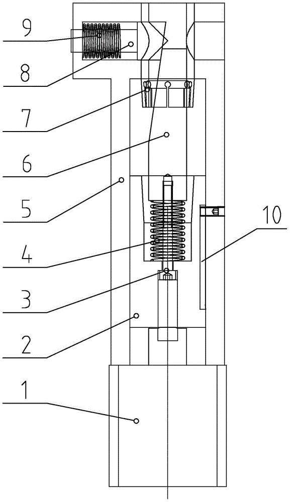
[0011] figure 1 Among them, it includes a linear oil cylinder 1, an inner cone sleeve 2, a connecting bolt 3, a spring 4, a machine base 5, an inclined shaft 6, an elastic collet 7, a support rod 8, a return spring 9, a limit groove 10, and the like.

[0012] Such as figure 1 As shown, the present invention is a floating support mechanism, including a machine base 5, a linear oil cylinder 1 is fixed on the bottom of the machine base 5, and an inner cone sleeve 2 is arranged on the machine base 5 corresponding to the upper position of the linear oil cylinder 1, The inner cone sleeve 2 can slide up and down relative to the machine base 5 under the push of the linear oil cylinder 1. A spring 4 is arranged in the upper conical cavity of the inner cone sleeve 2. Extend from the bottom of the inner cone sleeve 2, and the screw part of the connec...


PUM


Abstract

The invention relates to a floating supporting pressing device used in the fixture design process, in particular to a floating supporting mechanism. The floating supporting mechanism comprises a machine base; a linear oil cylinder is fixed to the bottom of the machine base, an inner-cone sleeve is arranged on the machine base, corresponding to the upper position of the linear oil cylinder, and can slide vertically relative to the machine base by being pushed by the linear oil cylinder, a spring is arranged in a conical cavity in the upper portion of the inner-cone sleeve, a wedge is arranged on the spring, and a connecting bolt stretches in from the bottom of the inner-cone sleeve. The floating supporting mechanism is simple in structure and reasonable in design; besides, the floating supporting mechanism can achieve dual locking and provide large and stable supporting force, which is mainly shown in the fact that the supporting force produced by self-locking of a supporting rod and the wedge is hard contact force instead of standard friction force provided by a supporting cylinder and the hard contact force is much larger and more stable than the friction force.

Description

technical field [0001] The invention relates to a floating support pressing device used in the fixture design process, in particular to a floating support mechanism. Background technique [0002] When designing the fixture, some processing parts of the workpiece need to be equipped with floating support and compression devices. Although there are standard pneumatic or hydraulic floating support cylinders, the structural principle is that the taper sleeve directly locks the support rod to provide support for the workpiece. The supporting force provided by this structure is limited, and the displacement generated when it is pressed again on the floating support structure is relatively large, and sometimes it is difficult to meet the requirements of use. Contents of the invention [0003] Aiming at the above problems, the present invention provides a floating support mechanism, which is a double locking mechanism and can provide strong and stable support force. [0004] Acco...

Claims


Application Information

Patent Timeline
Patent Type & Authority Patents(China)
IPC IPC(8): B25B11/00
CPCB25B11/00
Inventor 尤梅洲闫辉
Owner 无锡倍安杰机械科技有限公司
Why Eureka
Eureka Blog
Learn More