Pay-off rack of rigid conductor wire coil winding machine

A technology of a disc machine and a pay-off rack, applied in the field of pay-off racks, to achieve the effects of simple structure, precise positioning, and convenient use

Inactive Publication Date: 2014-04-09
QINGDAO CHENGSHUN CABLE
View PDF0 Cites 0 Cited by
  • Summary
  • Abstract
  • Description
  • Claims
  • Application Information

AI Technical Summary

Problems solved by technology

[0003] In order to overcome the defects of manual placement and positioning of rollers in the prior art, the present inve

Method used


Image

  • Pay-off rack of rigid conductor wire coil winding machine
  • Pay-off rack of rigid conductor wire coil winding machine
  • Pay-off rack of rigid conductor wire coil winding machine

Examples


Embodiment Construction

[0022] The preferred embodiments of the present invention will be described in detail below in conjunction with the accompanying drawings, so that the advantages and features of the present invention can be more easily understood by those skilled in the art, so as to define the protection scope of the present invention more clearly.

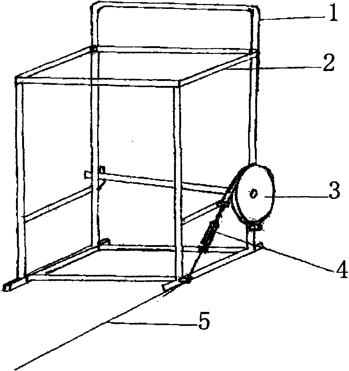
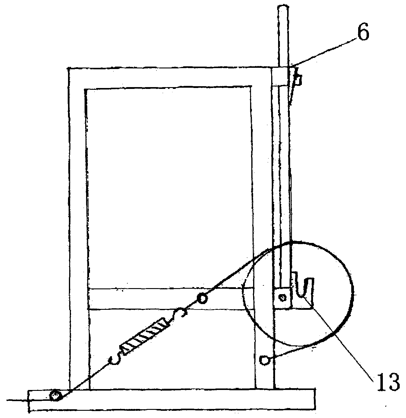
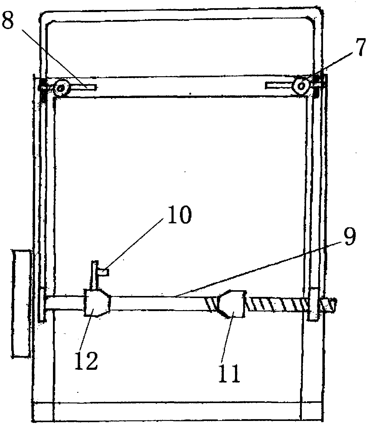
[0023] Such as Figure 1-3 As shown, the pay-off frame of the hard conductor electric wire coiling machine includes a frame 2, an upper roller device arranged on the frame 2, a positioning device and a brake device, and the upper roller device includes a frame arranged on one side of the frame 2, along the The loading and unloading handle 1 that the frame 2 rotates; the positioning device includes a roller positioning mechanism arranged on the loading and unloading handle 1; the braking device includes a brake disc 3 arranged at the lower end of the frame 2, a brake adjuster 4 wound on the brake disc 3, Brake pull rope 5 that is connected with br...


PUM


Abstract

The invention provides a pay-off rack of a rigid conductor wire coil winding machine. The pay-off rack comprises a machine frame, an upper roller device and a positioning device, wherein the upper roller device and the positioning device are arranged on the machine frame. The upper roller device comprises a loading and unloading handle which is arranged on one side of the machine frame and rotates around the machine frame. The positioning device comprises a roller positioning mechanism arranged on the loading and unloading handle. The pay-off rack of the rigid conductor wire coil winding machine has the advantages of being simple in structure and convenient to use, greatly lowering the labor intensity of workers, improving the positioning accuracy and the working efficiency, being capable of achieving accurate positioning of a roller in the axial direction and being particularly suitable for wires for civil buildings and other packing occasions where the wires thick in diameter and hard in conductor are needed.

Description

technical field [0001] The invention relates to the technical field of electric wire packaging, in particular to a pay-off frame for a hard conductor electric wire winding machine. Background technique [0002] The wire winding machine is an equipment for automatic wire arrangement, coiling, tying, and packaging of electric wires. It includes a pay-off frame, a wire arrangement device, and a coil-forming device. The pay-off frame in the prior art requires manual placement and positioning of the rollers. , The labor intensity of workers is high and the efficiency is low, which seriously affects the efficiency of wire packaging. Contents of the invention [0003] In order to overcome the defect that the rollers need to be placed and positioned manually in the prior art, the invention provides a pay-off stand for a wire and wire coiling machine that replaces the manual rollers and positioning. [0004] Technical scheme of the present invention is: [0005] A pay-off frame f...

Claims


Application Information

Patent Timeline
IPC IPC(8): B65H49/18
Inventor 曹增强
Owner QINGDAO CHENGSHUN CABLE
Why Eureka
Try Eureka