Supercharge Your Innovation With Domain-Expert AI Agents!

Jib, jib manufacturing method and concrete equipment

A manufacturing method and jib technology, which is applied in the field of jibs and concrete equipment, can solve problems such as the difficulty in forming box-shaped jib structures, and achieve the effects of low density, reduced weight, and reduced manufacturing difficulty

Active Publication Date: 2016-01-13
XUZHOU XCMG CONSTR MACHINERY CO LTD BUILDING MACHINERY
View PDF5 Cites 0 Cited by
  • Summary
  • Abstract
  • Description
  • Claims
  • Application Information

AI Technical Summary

Problems solved by technology

[0010] One of the purposes of the present invention is to propose a jib, a method of making the jib and concrete equipment, which solves the problem of difficulty in forming the box-shaped structure of the jib in the prior art

Method used


Image

  • Jib, jib manufacturing method and concrete equipment
  • Jib, jib manufacturing method and concrete equipment
  • Jib, jib manufacturing method and concrete equipment

Examples


Embodiment Construction

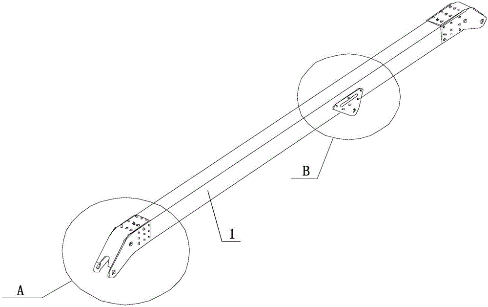
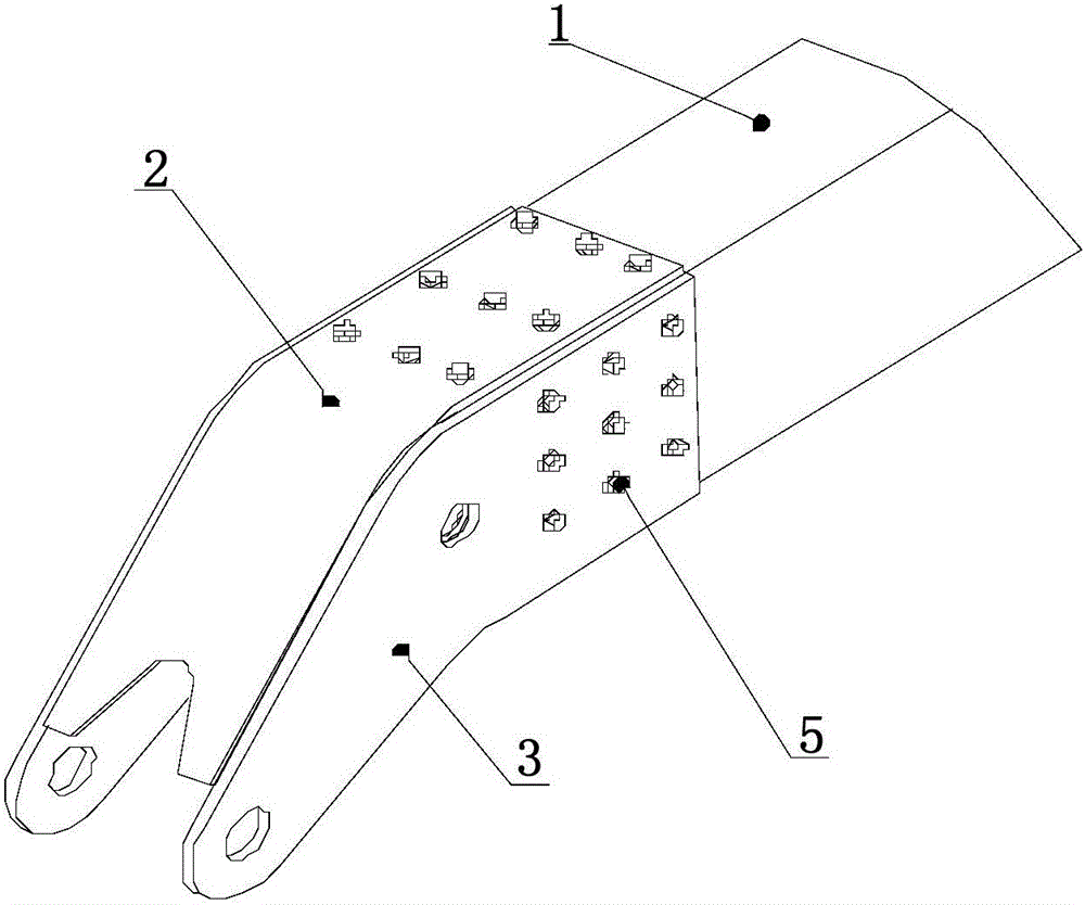
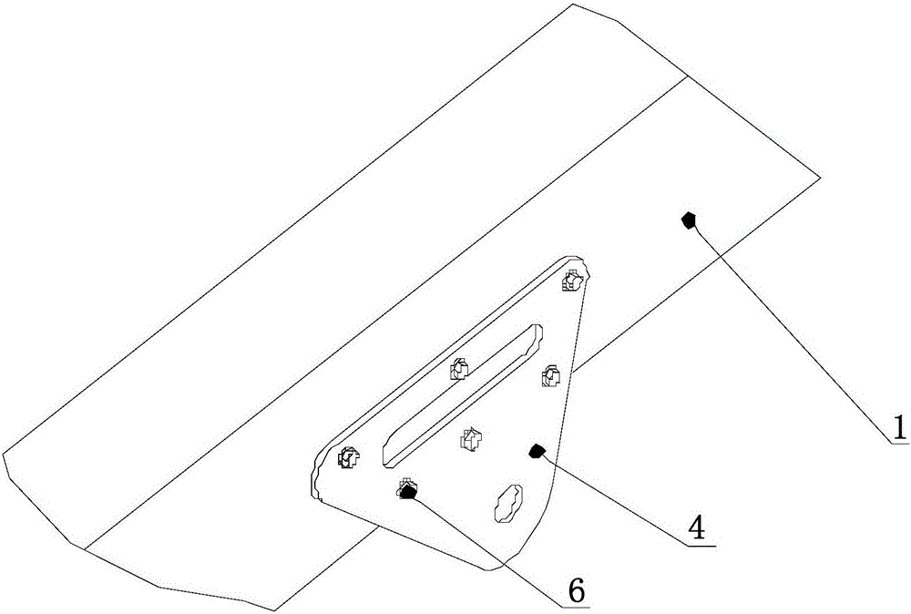
[0047] Below you can refer to the accompanying drawings Figure 1 to Figure 8 And the content of the text to understand the content of the present invention and the differences between the present invention and the prior art. The technical solution (including the preferred technical solution) of the present invention will be further described in detail below by way of the accompanying drawings and listing some optional embodiments of the present invention. It should be noted that: any technical feature and any technical solution in this embodiment are one or more of a variety of optional technical features or optional technical solutions. All the alternative technical features and alternative technical solutions of the present invention are cited, and it is not convenient for the implementation of each technical feature to emphasize that it is one of the optional multiple implementation modes, so those skilled in the art should know: Any technical features and any technical s...


PUM


Abstract

The invention discloses a cantilever crane, a cantilever crane manufacturing method and concrete equipment, and relates to the technical field of engineering machinery. The cantilever crane, the cantilever crane manufacturing method and the concrete equipment are used for solving the problem that in the prior art, a cantilever crane box-shaped structure is hard to form. The cantilever crane comprises an aluminum alloy box-shaped structure which comprises a first concave piece and a second concave piece, the first concave piece and the second concave piece are provided with open ends respectively, and the open end of the first concave piece and the open end of the second concave piece are in butt joint and fixed in a welding mode. The aluminum alloy box-shaped structure is formed by splicing the first concave piece and the second concave piece, the aluminum alloy box-shaped structure can be formed more easily, and manufacturing difficulty is lowered. In addition, the aluminum alloy box-shaped structure is made of aluminum alloy which is high in strength and small in density, and the weight of the whole cantilever crane can be lowered.

Description

technical field [0001] The invention relates to the technical field of engineering machinery, in particular to a boom, a method for manufacturing the boom and concrete equipment. Background technique [0002] At present, the booms of concrete pump trucks or concrete placing machines on the market are mostly box-shaped structures made of tailor-welded steel plates. Due to the rich accumulation of steel technology and mature manufacturing processes, steel is widely used on pump trucks. Boom frame. In the early stage of pump truck development, the length of the boom of the pump truck was on the order of millet, the weight was light, and the load on the pump truck chassis was small. [0003] However, with the development of concrete machinery itself and the urgent needs of high-rise building construction, ultra-long booms with a few meters in length have emerged as the times require. As the length of the boom increases, the quality of the steel boom seriously exceeds the stand...

Claims


Application Information

Patent Timeline
Patent Type & Authority Patents(China)
IPC IPC(8): E04G21/04
Inventor 徐怀玉沈千里张忠元王松田秋娟
Owner XUZHOU XCMG CONSTR MACHINERY CO LTD BUILDING MACHINERY
Features
  • R&D
  • Intellectual Property
  • Life Sciences
  • Materials
  • Tech Scout
  • Unparalleled Data Quality
  • Higher Quality Content
  • 60% Fewer Hallucinations
Learn More