Phase detection method for clock recovery and apparatuses
What is AI technical title?
AI technical title is built by Patsnap AI team. It summarizes the technical point description of the patent document.
一种时钟恢复、相位检测器的技术,应用在光通信领域,能够解决相位检测方法失效等问题
Active Publication Date: 2014-04-09
FUJITSU LTD
View PDF6 Cites 10 Cited by
Summary
Abstract
Description
Claims
Application Information
AI Technical Summary
This helps you quickly interpret patents by identifying the three key elements:
Problems solved by technology
Method used
Benefits of technology
Problems solved by technology
[0009] Embodiments of the present invention provide a phase detection method and device for clock recovery, to solve the problem in the case of a large frequency difference or line width, or when the transmitted signal has a spectral width close to the symbol rate (the spectral roll-off coefficient is small ) in the case of the Nyquist signal, the problem that the traditional phase detection method fails
Method used
Image
Click on the blue label to locate the original text in one second.
Reading with bidirectional positioning of images and text.
Examples
Embodiment 1
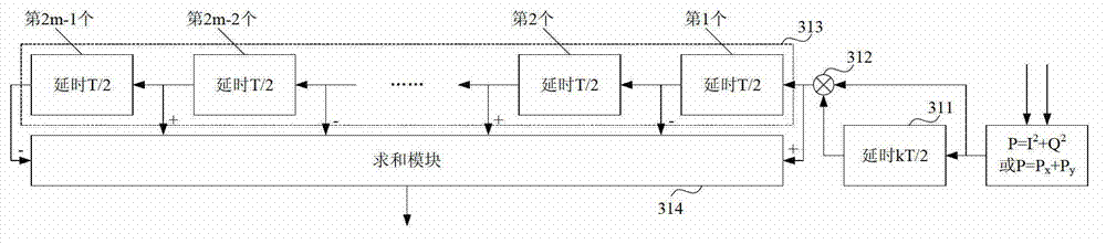
[0066] An embodiment of the present invention provides a phase detector, image 3 is the composition diagram of the phase detector, please refer to image 3 , the phase detector consists of:
[0067] A calculation unit 31, which calculates the phase difference according to the product of the received power at different times, so as to use the phase difference to perform clock recovery.
[0068] In this embodiment, the received power is the received power obtained when the input signal is sampled at a predetermined sampling rate. The predetermined sampling rate is twice the symbol rate.
[0069] In one embodiment, the calculation unit 31 can calculate the phase difference according to the following formula:
[0070] s 2 n = Σ i = 0 2 m - 1 ...
Embodiment 2
[0087] The embodiment of the invention also provides a clock recovery device. Figure 4 is a schematic diagram of the composition of the clock recovery device, please refer to Figure 4 , the clock recovery device includes: a voltage-controlled oscillator 41 and a phase detector 42, wherein:
[0088] The voltage-controlled oscillator 41 is used to drive the analog-to-digital converter for sampling. It can be realized by a traditional voltage-controlled oscillator, the content of which is incorporated herein, and will not be repeated here.
[0089] The phase detector 42 is connected with the voltage-controlled oscillator 41 for detecting phase difference. It can be realized by the phase detector described in Embodiment 1, the content of which is incorporated here, and will not be repeated here.
[0090] Through the clock recovery device of this embodiment, the phase difference detected by the phase detector of Embodiment 1 is used to control the sampling phase of the voltage...
Embodiment 3
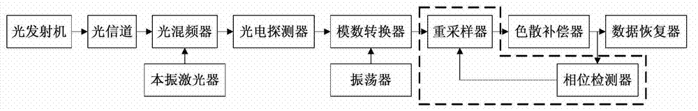
[0092] The embodiment of the present invention also provides a digital coherent receiver, and the digital coherent receiver is single-polarized. Figure 6 is a schematic diagram of the composition of the digital coherent receiver, please refer to Figure 5 , the digital coherent receiver includes: a coherent detector 51, an analog-to-digital converter 52, a dispersion compensator 53, a data restorer 54, and a clock recovery device 65, wherein:
[0093] The coherent detector 51 is used to convert the received optical signal into an electrical signal. For example, the coherent detector 51 may include a local oscillator laser, an optical mixer and a photodetector, which converts the received optical signal into an electrical signal by using the local oscillator laser, the optical mixer and the photodetector. In this embodiment, the coherent detector 51 can be implemented by a traditional coherent detector, the content of which is incorporated herein, and will not be repeated her...
PUM
Abstract
The embodiment of the invention provides a phase detection method for clock recovery and apparatuses. The apparatuses include a phase detector including a calculating unit. The calculating unit calculates a phase difference according to the product of receiving powers at different times so as to carry out clock recovery by using the phase difference; and the receiving powers are obtained by carrying out sampling on input signals by a predetermined sampling rate, wherein the predetermined sampling rate is twice larger than the symbol rate. According to the method and the apparatuses, because the phase difference is calculated according to the product of the receiving powers at different times, a problem that the traditional phase detection method is invalid under the circumstances that the large frequency difference or line width exists or the sending signal is the Nyquist signal with the spectral width close to the symbol rate can be solved.
Description
technical field [0001] The present invention relates to the technical field of optical communication, in particular to a phase detection method for clock recovery, a phase detector, a clock recovery device including the phase detector, and a coherent optical receiver including the clock recovery device. Background technique [0002] In a communication system, the signal at the sending end reaches the receiving end through channel transmission. During this process, the signal waveform is often severely distorted. At the receiving end, if no processing is done, the sent data cannot be obtained. In an actual receiver, clock and data recovery (CDR) is usually performed. Among them, the purpose of clock recovery (clock recovery, CR) is to generate a clock signal locally, and the frequency and phase of the clock signal are consistent with the frequency and phase of the symbol change of the received signal. [0003] figure 1 and figure 2 is a schematic diagram of a coherent op...
Claims
Application Information
Patent Timeline
Application Date:The date an application was filed.
Publication Date:The date a patent or application was officially published.
First Publication Date:The earliest publication date of a patent with the same application number.
Issue Date:Publication date of the patent grant document.
PCT Entry Date:The Entry date of PCT National Phase.
Estimated Expiry Date:The statutory expiry date of a patent right according to the Patent Law, and it is the longest term of protection that the patent right can achieve without the termination of the patent right due to other reasons(Term extension factor has been taken into account ).
Invalid Date:Actual expiry date is based on effective date or publication date of legal transaction data of invalid patent.

