A high-speed railway power supply arm joint trip protection method based on current characteristics

A technology for current protection and high-speed railways, applied to emergency protection circuit devices, electrical components, etc., can solve problems such as unsatisfactory protection selectivity, unrecognizable end high-resistance faults, high-speed EMU load current, etc., to improve protection Sensitivity, prevention of misjudgment, small power failure range

Active Publication Date: 2016-04-06
SOUTHWEST JIAOTONG UNIV
View PDF6 Cites 0 Cited by
  • Summary
  • Abstract
  • Description
  • Claims
  • Application Information

AI Technical Summary

Problems solved by technology

[0004] Problem 1. The existing protection method only considers the measured impedance and current of the substation. When a fault occurs between the AT station and the partition station, it is impossible to judge whether the fault occurred on the uplink power supply arm or the downlink power supply arm. Therefore, when any location occurs When a fault occurs, the substation will jump off the two power supply arms, and the power failure range is large, which cannot meet the selectivity of protection
[0005] Problem 2. Due to the need to realize fault isolation through the cooperation of substation, AT substation and partition substation reclosing, it takes a long time to restore power supply
[0006] Problem 3. Due to the large load current of the high-speed EMU, the existing protection method should be set according to the maximum load current where the substation is avoided. The large setting value makes it impossible to identify the high-resistance fault at the end

Method used


Image

  • A high-speed railway power supply arm joint trip protection method based on current characteristics
  • A high-speed railway power supply arm joint trip protection method based on current characteristics
  • A high-speed railway power supply arm joint trip protection method based on current characteristics

Examples


Embodiment Construction

[0024] The present invention will be further described below in conjunction with the accompanying drawings and specific implementation. The drawings and specific embodiments do not limit the scope of protection claimed by the present invention.

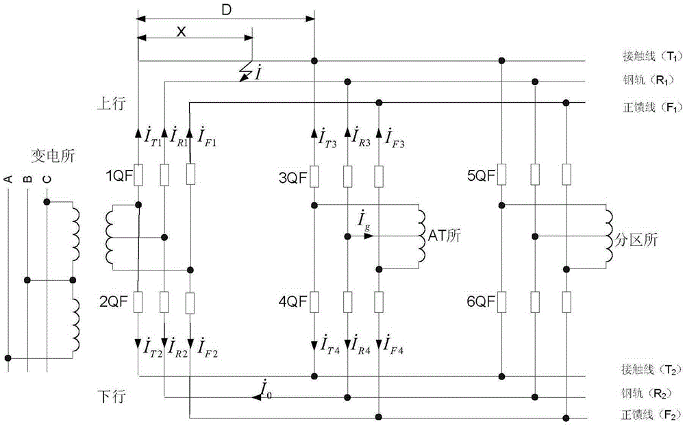
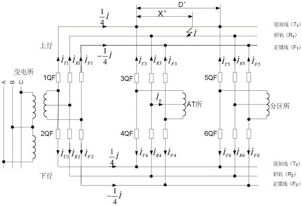
[0025] When a short-circuit fault occurs between the substation and the AT station, in the fault section, the upstream and downstream T 1 with T 2 , F 1 with F 2 , R 1 with R 2 The loops are formed respectively, and three loop voltage equations can be obtained:

[0026] I · T 1 Z T X - I · T 3 Z ...


PUM


Abstract

The invention discloses a high-speed railway supply arm shunt tripping protection method based on the current characteristics. The method is realized through current protection elements distributed in a substation, an AT station and a subarea station and through a communication network. Each current protection element can transmit shunt tripping instructions to other current protection elements or receive the shunt tripping instructions from other current protection elements on the same supply arm through the communication network to rapidly isolate a fault supply arm. When a fault happens between the substation and the AT station, the current protection element of the substation recognizes a faulty line through the adoption of the current ratio criterion and over-current criterion, and the current protection element of the AT station recognizes the faulty line through the adoption of the directional over-current criterion. When a fault happens between the AT station and the subarea station, the current protection element of the AT station and the current protection element of the subarea station recognize the faulty line through the adoption of the directional over-current criterion. When the fault of any current protection element is detected, a breaker of the fault supply arm in the station is tripped off, a shunt tripping instruction is transmitted to the other current protection elements on the same supply arm, the other current protection elements receive the shunt tripping instruction and then tripp off the corresponding breakers, and consequently the fault supply arm is rapidly isolated, and power supply of the other supply arm which is connected with the fault supply arm in parallel can not be influenced.

Description

technical field [0001] The invention belongs to the field of high-speed electrified railway traction power supply system, and the invention relates to the protection of electrified railway traction network adopting the power supply mode of full parallel autotransformer (AT). Background technique [0002] In order to meet the needs of high-speed EMUs for power supply capacity, my country's high-speed railways are all in parallel AT power supply mode. However, compared with normal-speed railways, the structure of the traction network under the full-parallel AT power supply mode is more complex, there are more types of faults, and the requirements for relay protection are higher. However, the traction load has the characteristics of mobility and impact, and the structure and power supply mode of the traction network are also very different from the power system. The methods in the power system, such as fault component method, model identification method, comprehensive impedance...

Claims


Application Information

Patent Timeline
Patent Type & Authority Patents(China)
IPC IPC(8): H02H7/28
Inventor 韩正庆刘淑萍高仕斌
Owner SOUTHWEST JIAOTONG UNIV
Why Eureka
Try Eureka