Winding apparatus

A technology of winding device and imaginary wire, applied in electromechanical devices, manufacturing motor generators, electrical components, etc., can solve problems such as winding slack, and achieve the effect of reducing position changes

Active Publication Date: 2014-04-09
NIDEC MACHINERY
View PDF6 Cites 10 Cited by
  • Summary
  • Abstract
  • Description
  • Claims
  • Application Information

AI Technical Summary

Problems solved by technology

[0003] However, when the posture is changed in this thread processing process, there is a risk that the position of the end of the nozzle changes before and after the change, and the winding slack may occur.

Method used


Image

  • Winding apparatus
  • Winding apparatus
  • Winding apparatus

Examples


no. 1 approach

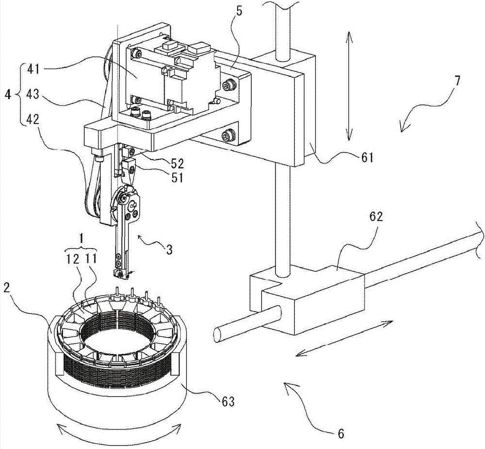
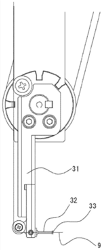
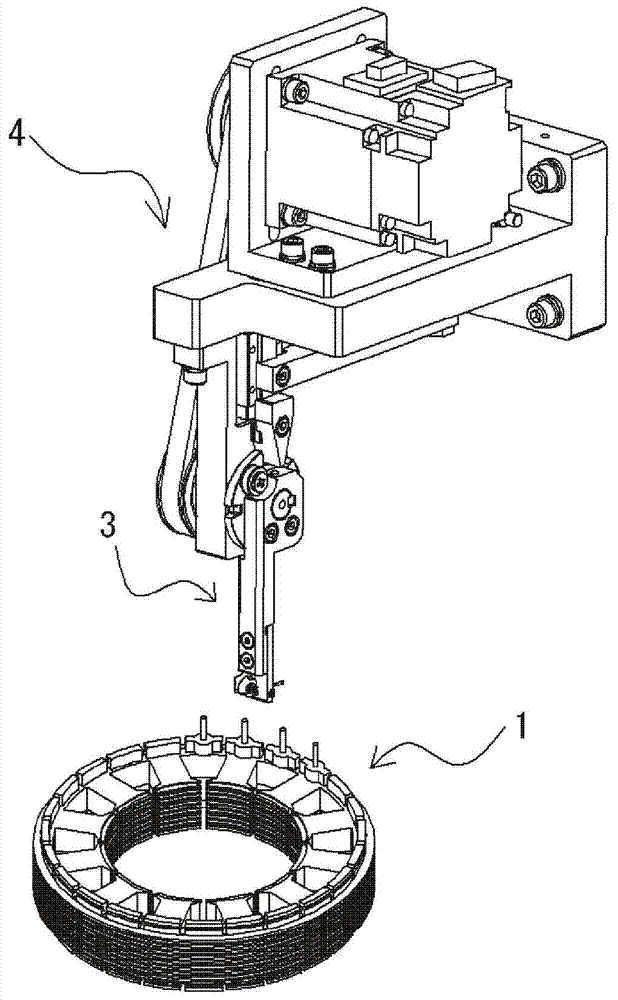
[0020] figure 1 It is a perspective view of the winding device concerning this invention. Such as figure 1 As shown, the winding device includes a core holding portion 2 , an arm portion 3 , an arm rotation mechanism 4 , and a support portion 5 . The core holder 2 holds the annular core 1 . The arm portion 3 has a columnar shape having a hole or a groove-shaped guide portion through which the wire rod passes at the distal end. The arm rotation mechanism 4 rotates the arm 3 near the proximal end to change the posture of the arm 3 . The support portion 5 supports the arm rotation mechanism 4 . The winding device further includes a relative movement mechanism 6 for changing the relative position of the support portion 5 and the iron core 1 . In this example, the relative movement mechanism 6 also functions as a support portion moving mechanism 7 that moves the support portion 5 . The relative movement mechanism 6 includes a vertical movement mechanism 61 that moves the supp...


PUM


Abstract

The invention discloses a winding apparatus that winds thread material to a stator core. In order to make the end of a thread nozzle on an arm moves slightly when the arm changes gesture, when an arm rotating mechanism makes the arm rotate in one direction, a supporting part mobile mechanism rotates synchronously in the same direction with the arm, so that the rotating shaft of the arm rotating mechanism rotates in the same direction by taking a first imaginary thread passing through the thread nozzle as the rotating shaft.

Description

technical field [0001] The invention relates to a winding device. Background technique [0002] Conventionally, a wire winding device has been widely used to wind a wire for forming a coil around the poles of a multi-pole armature (motor core). Here, before and after the winding process of winding the wire to the poles of the multi-pole armature, the clamping process of clamping the wire end into the wire end clamping device provided on the workpiece holding jig, and the clamping of the wire end are often carried out simultaneously. A plurality of wire processing steps such as a connection step connected to a connection pin arranged on a workpiece, and a jumper wire forming step of forming a jumper wire in the middle of the wire material other than the wire winding portion. In such a thread processing step, the posture of the arm to which the nozzle is attached may be changed to a state different from that of the thread winding step to perform the thread processing step (fo...

Claims


Application Information

Patent Timeline
Patent Type & Authority Applications(China)
IPC IPC(8): H02K15/08
Inventor 林利久山根一泰长石佳弘
Owner NIDEC MACHINERY
Why Eureka
Try Eureka