Elastically deformable flange locator arrangement and method of reducing positional variation

a technology of flange locator and deformation, applied in the direction of fixed installation, transportation and packaging, light and heating equipment, etc., can solve problems such as poor fit, and achieve the effect of reducing the positional variation of mated components

Active Publication Date: 2016-03-08
GM GLOBAL TECH OPERATIONS LLC
View PDF430 Cites 2 Cited by
  • Summary
  • Abstract
  • Description
  • Claims
  • Application Information

AI Technical Summary

Benefits of technology

[0005]In yet another exemplary embodiment, a method of reducing positional variation of mated components is provided. The method includes forming a first engagement surface in a first component. The method also includes contacting a second engagement surface located proximate a perimeter of a second component with the first engagement surface, wherein the second component comprises a first portion and a second portion, the second portion extending relatively perpendicularly from the first portion, wherein the second portion comprises the second engagement surface. The method further includes elastically deforming second portion of the second component upon contacting the second engagement surface with the first engagement surface. The method yet further includes performing an elastic averaging of the elastic deformation over the second engagement surface, wherein upon reaching a fully engaged position of the second portion of the second component a fitted alignment between the first component and the second component is established.

Problems solved by technology

As a result, the occurrence of significant positional variation between the mated components, which contributes to the presence of undesirably large and varying gaps and otherwise poor fit may occur.

Method used


Image

  • Elastically deformable flange locator arrangement and method of reducing  positional variation
  • Elastically deformable flange locator arrangement and method of reducing  positional variation
  • Elastically deformable flange locator arrangement and method of reducing  positional variation

Examples


first embodiment

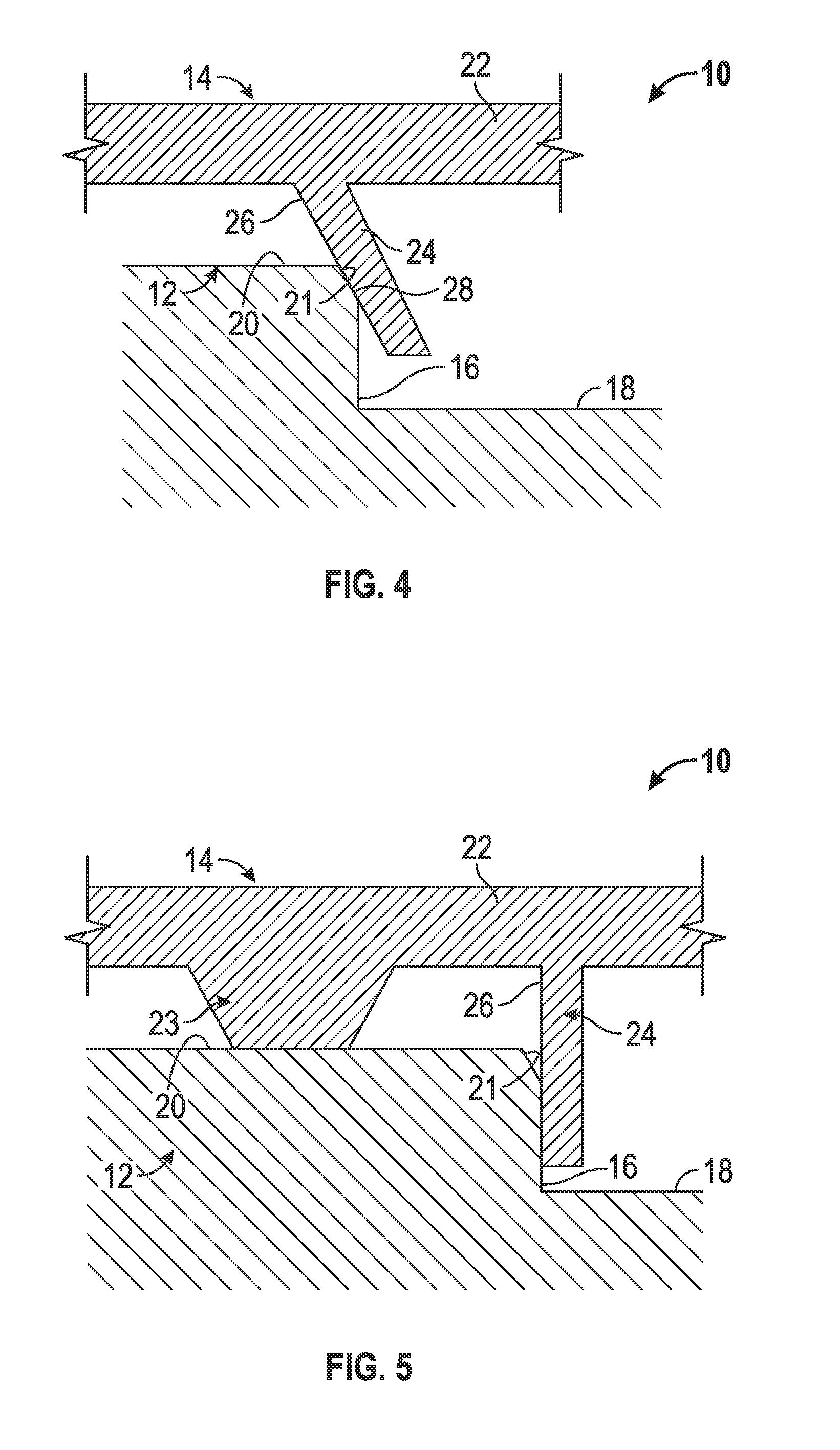
[0020]Referring now to FIG. 4, the elastically deformable flange locator arrangement 10 is illustrated in greater detail. Specifically, a cross-sectional view is shown to illustrate an engagement region between the first component 12 and the second component 14 of the elastically deformable flange locator arrangement 10. In the illustrated embodiment, the first component 12 includes a first engagement surface 16 that extends in a peripheral manner around the first component 12. In one embodiment, the first engagement surface 16 extends continuously around a portion of the first component 12, typically proximate a perimeter of the first component 12, but the first engagement surface 16 may be disposed inwardly at various contemplated distances, depending on the particular application. The first engagement surface 16 comprises a first engagement surface length, also referred to herein as a first perimeter. In the illustrated embodiment, the first engagement surface 16 is disposed prox...

fourth embodiment

[0034]Referring to FIGS. 8 and 9, additional embodiments of the elastically deformable flange locator arrangement 10 are shown. Both embodiments are similar to the fourth embodiment described above in conjunction with FIG. 7, based on the presence of the recess 54 disposed between the second portion 24 and the third portion 50 of the second component 14. In both additional embodiments, the second engagement surface 26 and the third engagement surface 52 are aligned relatively perpendicularly to the first portion 22 of the second component 14 and to the base wall 18 of the first component 12.

[0035]As with previous embodiments, the first component 12 also includes the chamfer portion 21 for lead-in purposes, but the second engagement surface 26 of the second portion 24 primarily engages the first channel engagement surface 16 along a portion of the first channel engagement surface 16 that is similarly aligned in a substantially orthogonal manner to the base wall 18. Similarly, the thi...


PUM

PropertyMeasurementUnit
perimeteraaaaaaaaaa
widthaaaaaaaaaa
distanceaaaaaaaaaa

Abstract

An elastically deformable flange locator arrangement includes a first component having a first engagement surface. Also included is a second component configured to be mated with the first component. Further included is a first portion of the second component. Yet further included is a second portion of the second component extending relatively perpendicularly from the first portion proximate a perimeter of the first portion, the second portion having a second engagement surface, wherein the second portion is configured to elastically deform at a first interface upon contact between the first engagement surface and the second engagement surface.

Description

FIELD OF THE INVENTION[0001]The present invention relates to an elastically deformable flange locator arrangement for aligning components relative to each other, as well as a method of reducing positional variation for components of the elastically deformable flange locator arrangement.BACKGROUND[0002]Currently, components which are to be mated together in a manufacturing process are subject to positional variation based on the mating arrangements used to assemble the components. One common arrangement includes components mutually located with respect to each other by 2-way and / or 4-way male alignment features, typically upstanding bosses, which are received into corresponding female alignment features, typically apertures in the form of openings and / or slots. Alternatively, adhesives or welding processes may be employed to mate parts. Regardless of the precise mating arrangement, a clearance typically exists between at least a portion of the mated components, which is predetermined...

Claims


Application Information

Patent Timeline
Patent Type & Authority Patents(United States)
IPC IPC(8): B60Q1/04F16B17/00F21S8/10
CPCB60Q1/045F16B17/00F21S48/1208F21S48/1216F21S48/1233Y10T29/49908Y10T403/1616F21S41/29F21S41/28F21S41/295
Inventor COLOMBO, JOELMORRIS, STEVEN E.RICHARDSON, MICHAEL D.
Owner GM GLOBAL TECH OPERATIONS LLC
Why Eureka
Try Eureka