Processing apparatus using focused charged particle beam

a technology of charged particle and processing apparatus, applied in the field of processing apparatus, can solve the problems of large equipment scale, long time to stabilize the temperature of a sample, and difficult high-precision processing, and achieve the effect of reducing the position change of the mount stag

Active Publication Date: 2007-02-22
HITACHI HIGH TECH SCI CORP
View PDF2 Cites 3 Cited by
  • Summary
  • Abstract
  • Description
  • Claims
  • Application Information

AI Technical Summary

Benefits of technology

[0039] The processing apparatus using the focused charged particle beam according to the invention can promptly cool the sample and can relax a thermal drift by the special mount stage which can reduce the sample and the sample mount part in size and can reduce the position change of the mount stage caused by thermal expansion and contraction.

Problems solved by technology

In addition, charged particle beam irradiation often damages a sample, but it is reported that a sample is cooled to reduce damage caused by a charged particle beam.
However, when the entire sample stage is cooled, problems arise that it takes a long time to stabilize the temperature of a sample, and that cooling the entire sample tends to generate a temperature gradient and thus a drift tends to occur caused by thermal expansion and contraction, causing highly accurate processing to be difficult.
However, the equipment becomes in a large scale, and the method is not a convenient method for solving problems.

Method used


Image

  • Processing apparatus using focused charged particle beam
  • Processing apparatus using focused charged particle beam
  • Processing apparatus using focused charged particle beam

Examples


first embodiment

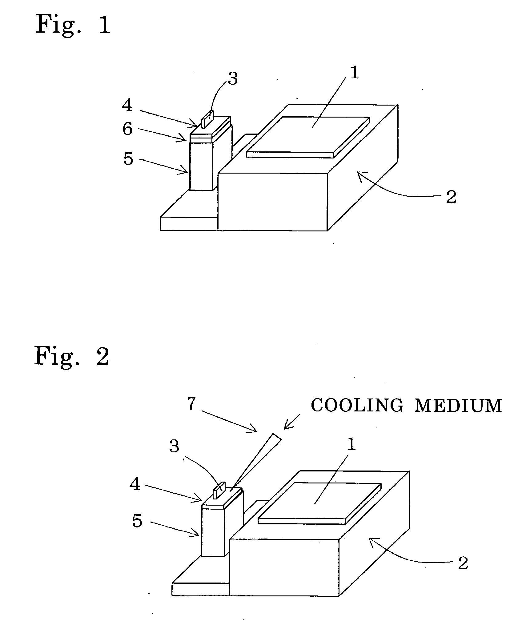
[0048] FIGS. 1 to 3 show the detail of a micro sample stage and a sample stage of a processing apparatus using a focused charged particle beam according to a first embodiment of the invention. The first embodiment is an exemplary implementation provided with the micro sample stage and the sample stage.

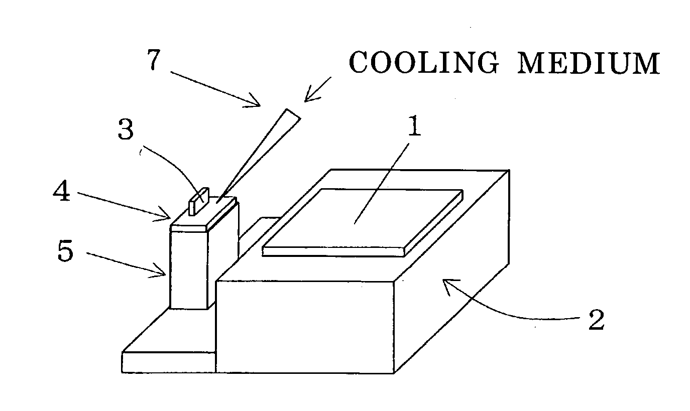
[0049]FIG. 1 shows the case in which an electronic cooling mechanism is used for a cooling unit. FIG. 2 shows the case in which a probe filled with a cooling medium is used for a cooling unit. FIG. 3 shows the case in which a cooling tube containing a cooling medium is used for a cooling unit.

[0050] As shown in FIGS. 1 to 3, the processing apparatus using the focused charged particle beam according to the embodiment is provided with a sample 1 which is processed with a focused charged particle beam, and a sample stage 2 on which the sample 1 is placed. A micro sample 3 which is cut out of the sample 1 with the focused charged particle beam is placed on a micro mount part 4. The micro...

second embodiment

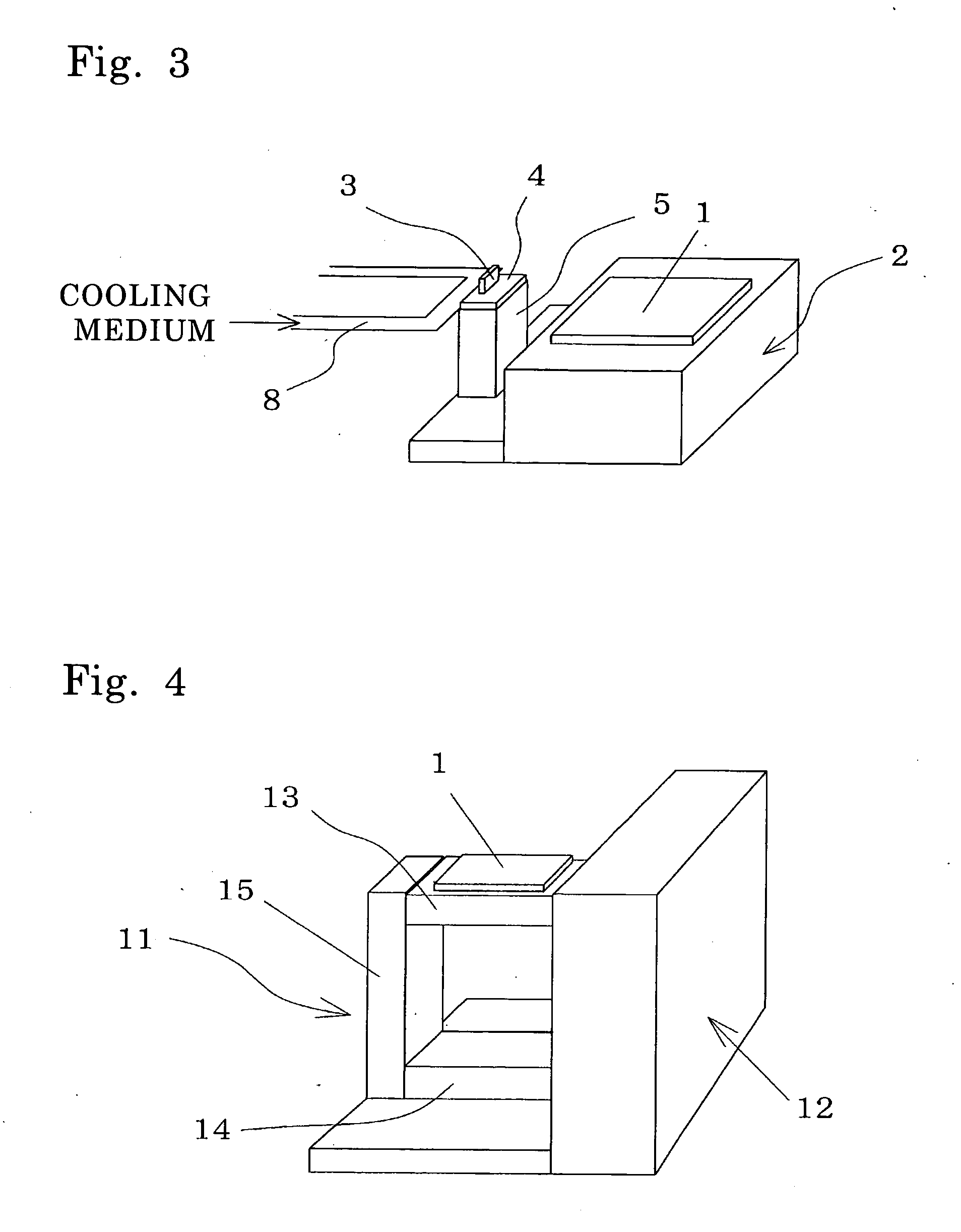
[0053] FIGS. 4 to 5 show the detail of a special mount stage and a special mount stage support of a processing apparatus using a focused charged particle beam according to a second embodiment of the invention. The second embodiment is an exemplary implementation provided with the special mount stage and the special mount stage support.

[0054]FIG. 4 shows a perspective view depicting the special mount stage and the special mount stage support, and FIG. 5 shows a diagram illustrative of the special mount stage and the special mount stage support.

[0055] As shown in FIGS. 4 to 5, the processing apparatus using the focused charged particle beam according to the embodiment is provided with a special mount stage 11 on which a sample 1 processed with a focused charged particle beam is placed, and a special mount stage support 12 in an L-shape which supports the special mount stage 11. The special mount stage 11 is configured of a top plate 13 on which the sample is directly placed, a botto...

third embodiment

[0056]FIG. 6 relates to a third embodiment according to the invention, which shows a perspective view depicting a micro sample stage and a sample stage in which the special mount stage and the special mount stage support according to the second embodiment are disposed on the micro sample stage according to the first embodiment of the invention. The third embodiment is an exemplary implementation provided with the special mount stage and the special mount stage support on the sample stage.

[0057] As shown in FIG. 6, the embodiment shows an example that the special mount stage support 12 shown in FIGS. 4 to 5 is supported by the micro sample stage 5 according to the first embodiment. A sample 1 is placed on a sample stage 2, a micro sample stage 5 is supported by the sample stage 2, and a special mount stage support 12, a special mount stage 11 and a micro sample 3 are supported by the micro sample stage 5. Sine the sample itself is minute, a drift caused by thermal contraction is sma...


PUM


Abstract

A sample to be observed or processed with a focused charged particle beam is formed small, and only the micro sample is locally cooled. Alternatively, a sample mount part is used which has the structure that can relax a thermal drift.

Description

BACKGROUND OF THE INVENTION [0001] The present invention relates to a processing apparatus which has a cooling sample stage allowing reducing a thermal drift and which uses a focused charged particle beam. [0002] In recent years, in preparing a sample for an electronic microscope in order to observe a particular area such as observing a defective part of a semiconductor device, a method of using a charged particle beam is utilized. More specifically, a sample is processed in such ways that ions are accelerated, focused and applied onto a particular area of a device or the like to be an observation target and a desired slice is cut out, and that a sample is cut to provide desired depth or a shape in order to expose an observation part when an observation target exists inside. [0003] When a sample to be an observation target is a material vulnerable to heat, it is necessary to process the sample while it is being cooled. In addition, charged particle beam irradiation often damages a s...

Claims


Application Information

Patent Timeline
Patent Type & Authority Applications(United States)
IPC IPC(8): H01J37/20
CPCG01N1/32
Inventor YAMAMOTO, YOTAKAHASHI, HARUOFUJII, TOSHIAKI
Owner HITACHI HIGH TECH SCI CORP
Why Eureka
Try Eureka