
Actuating units for automotive applications

An executive unit, motor vehicle technology, applied in the application of locks, special positions of vehicles, vehicle locks, etc., to achieve the effect of eliminating motor noise

Active Publication Date: 2016-02-24
KIEKERT AG
View PDF8 Cites 0 Cited by
  • Summary
  • Abstract
  • Description
  • Claims
  • Application Information

AI Technical Summary

Problems solved by technology

[0007] The technical problem to be solved by the present invention is to further improve such an actuator unit for automotive applications in such a way that the noise characteristics and the orientation of the motor relative to the transmission are optimized without or practically without malfunctions

Method used


Image

  • Actuating units for automotive applications
  • Actuating units for automotive applications
  • Actuating units for automotive applications

Examples


Embodiment Construction

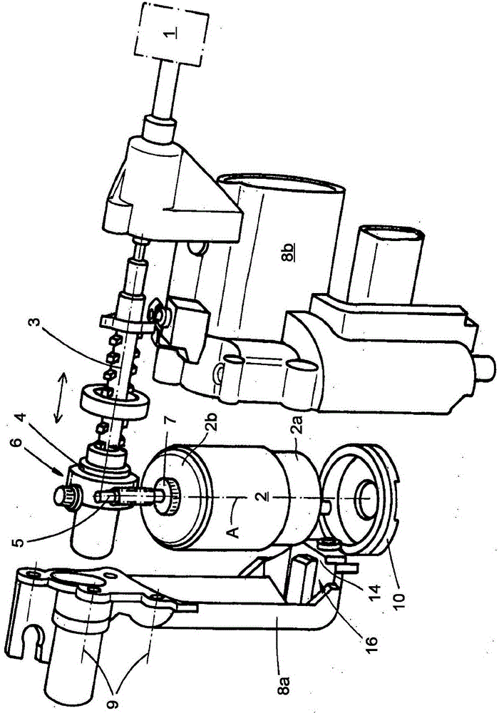
[0027]The drawing shows an actuating unit for a motor vehicle application. By way of example and not limitation, a motor vehicle application relates to performing functions in relation to one or more motor vehicle door locks 1 . In fact, the actuating unit shown can be used to activate a closing device in such a motor vehicle door lock 1 , as described, for example, in DE 101 12 120 B4. Of course this should be understood as merely exemplary and non-limiting.

[0028] In order to be able to carry out the described actuating movement or loading of the closing device specifically in the motor vehicle door lock 1 , the actuating unit has, in its basic structure, a drive 2 and an actuating part 3 , 4 , which is designed here as a straight line. Execute components 3, 4. The actuator or linear actuators 3 , 4 are acted upon by the drive 2 in order to actuate the closing device on the motor vehicle door lock 1 .

[0029] Furthermore, housings 8a, 8b are realized. The drive device...


PUM


Abstract

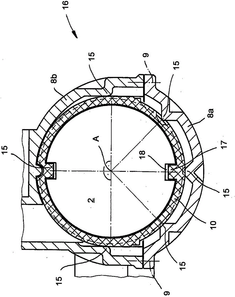
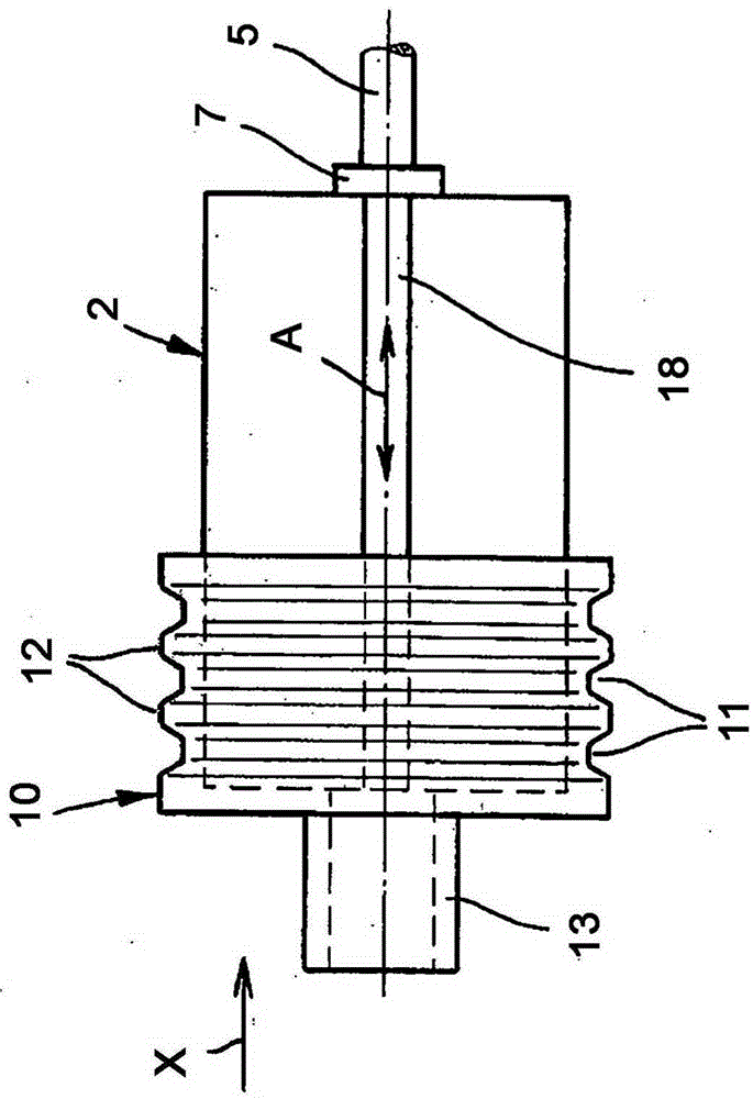
The invention relates to an actuating unit for technical motor vehicle applications, in particular a motor vehicle door lock (1). The basic structure of the actuating unit comprises a housing (8a, 8b), a driving device (2) arranged in said housing (8a, 8b), an actuating part (3, 4) capable of being loaded by said driving device (2) ), and at least one rubber bearing (10) for said driving device (2). According to the invention, the housing ( 8 a , 8 b ) is equipped with receiving projections ( 15 ) distributed in the circumferential direction of the rubber bearing ( 10 ) in the region of the rubber bearing receiver ( 16 ).

Description

technical field [0001] The invention relates to an actuating unit for a technical motor vehicle application, in particular for a motor vehicle door lock, which has a housing, a drive arranged in the housing, an actuating component that can be acted upon by the drive and at least A rubber bearing for the drive unit. Background technique [0002] An execution unit of the aforementioned structure is described in DE 10 2009 036 835 A1 of the applicant. In fact, the actuator here is designed as a linear actuator and is used to load the closing device. The closing device may be the device described in DE10112120B4. [0003] In the scope of DE 10 2009 036 835 A1, the rubber bearing is mainly used to receive and surround the base of the drive designed as an electric motor. In addition to this rubber bearing, the drive also has a pressure bearing. In this way, the rotational movement provided by the drive on its output shaft is transmitted perfectly, precisely and with little vib...

Claims


Application Information

Patent Timeline
Patent Type & Authority Patents(China)
IPC IPC(8): B60N2/02H02K5/24E05B83/36
CPCE05B81/25H02K5/24H02K7/081H02K7/1166Y10T292/1021B60N2/02246E05C1/06F16F15/08
Inventor F·布卢门塔尔W·施拉布斯C·特普费尔
Owner KIEKERT AG
Learn More