Supercharge Your Innovation With Domain-Expert AI Agents!

Steamturbine comprising a dummy piston

A thrust balancing piston and steam turbine technology, which is applied to steam engine devices, mechanical equipment, engine functions, etc., can solve the problems of unfavorable steam turbines and limited service life, and achieve the effects of improving cooling effect, fast and low-cost production

Inactive Publication Date: 2014-04-09
SIEMENS AG
View PDF5 Cites 1 Cited by
  • Summary
  • Abstract
  • Description
  • Claims
  • Application Information

AI Technical Summary

Problems solved by technology

The problem arises here that when using the previously customary turbine materials, the ever-increasing demands placed on the steam turbine body due to the increased steam parameters can lead to unfavorable, service-limiting thermal loads on the steam turbine
Therefore, it is almost no longer possible to manufacture such steam turbines economically

Method used


Image

  • Steamturbine comprising a dummy piston
  • Steamturbine comprising a dummy piston

Examples


Embodiment Construction

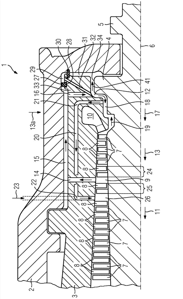
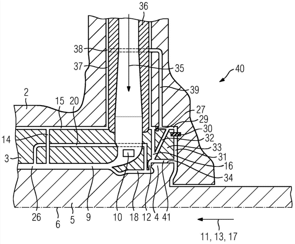
[0020] exist figure 1 A cross section through a steam turbine 1 is depicted in . The steam turbine 1 has an outer casing 2 and an inner casing 3 . The inner housing 3 and the outer housing 2 have live steam supply channels, which are in the figure 2 explained in detail. Inside the inner housing 3 is arranged a rotor 5 with a thrust balancing piston 4 in a rotatably mounted manner. The rotor is generally designed rotationally symmetrically about the axis of rotation 6 . The rotor 5 includes a plurality of rotor blades 7 . The inner housing 3 has a plurality of guide vanes 8 . A flow channel 9 is formed between the inner housing 3 and the rotor 5 . The flow channel 9 comprises a plurality of blade stages, each of which is formed by a row of rotor blades 7 and a row of guide blades 8 .

[0021] The live steam flows via the live steam supply channel into the inlet opening 10 and from there flows through the flow channel 9 in a flow direction 11 which runs substantially par...


PUM


Abstract

The invention concerns a cooling mechanism for a steam turbine (1), which envisages, in the area of the valve connection (40) a cooling channel (37), into which cooling steam flows from the flow channel (9), the steam then being fed as cooling steam in the area of the thrust balance piston (4).

Description

technical field [0001] The invention relates to a steam turbine with an outer casing and an inner casing, wherein a rotor comprising a plurality of working blades with thrust balancing pistons is arranged rotatably mounted inside the inner casing, wherein the inner casing There is an inner housing end region formed around the thrust balancing piston, wherein a seal seals a third pressure chamber arranged between the inner housing region and the outer housing, wherein the inner housing has a feed channel which will The first pressure chamber is connected with the thrust balance piston front chamber, and the thrust balance piston front chamber is arranged between the thrust balance piston and the inner housing. Background technique [0002] For the purposes of this application, a steam turbine is understood to be any turbine or part-turbine through which a working medium in the form of steam flows. In contrast, gas turbines are fed gas and / or air as the working medium, but th...

Claims


Application Information

Patent Timeline
Patent Type & Authority Applications(China)
IPC IPC(8): F01D3/04
CPCF05D2260/20F01K3/04F05D2220/31F01D3/04
Inventor 马丁纳·霍尔德克里斯蒂安·伦兹诺贝特·皮珀鲁道夫·波特多米尼克·施莱胡贝尔乌韦·赞德
Owner SIEMENS AG
Features
  • R&D
  • Intellectual Property
  • Life Sciences
  • Materials
  • Tech Scout
  • Unparalleled Data Quality
  • Higher Quality Content
  • 60% Fewer Hallucinations
Learn More