A dynamic shaft seat of a viscosity machine

A viscosity machine and shaft seat technology, which is applied in the direction of mechanical equipment, bearing components, shafts and bearings, etc., can solve problems such as unstable operation of the viscosity machine, affecting product quality, and unreasonable structure, so as to achieve reasonable structure, meet production needs, Design the right effect

Inactive Publication Date: 2016-04-06
PINGHU YONGGUANG MACHINERY PARTS
View PDF6 Cites 0 Cited by
  • Summary
  • Abstract
  • Description
  • Claims
  • Application Information

AI Technical Summary

Problems solved by technology

[0003] In order to overcome the defects of the ordinary viscosity machine's moving shaft seat, such as unstable operation, inaccurate measurement, large errors, and affecting product quality, due to wrong design and unreasonable structure, the invention provides a moving shaft of the viscosity machine Seat, the dynamic shaft seat of the viscosity machine is an important part of the viscosity machine. The design is correct and the structure is reasonable, which can make the viscosity machine work stably, ensure accurate measurement, stable performance, high precision, and detection in place.

Method used


Image

  • A dynamic shaft seat of a viscosity machine
  • A dynamic shaft seat of a viscosity machine
  • A dynamic shaft seat of a viscosity machine

Examples


Embodiment Construction

[0011] The present invention will be further described below in conjunction with accompanying drawing:

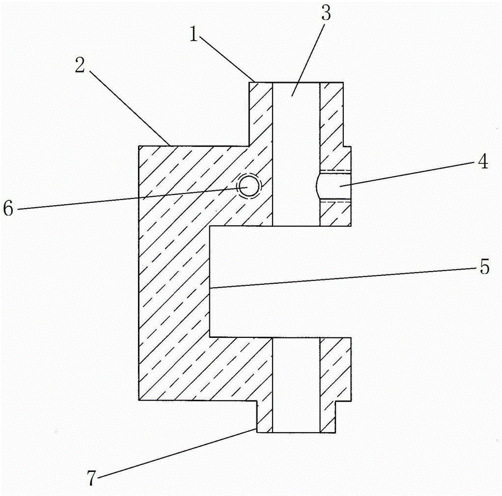
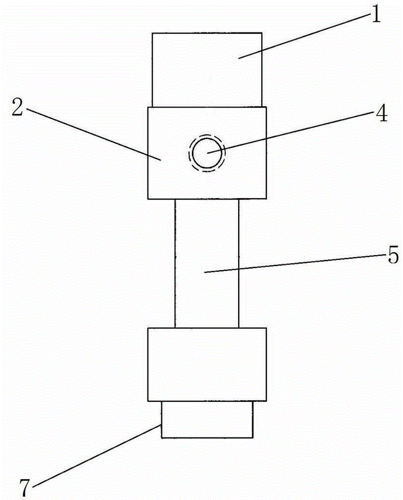
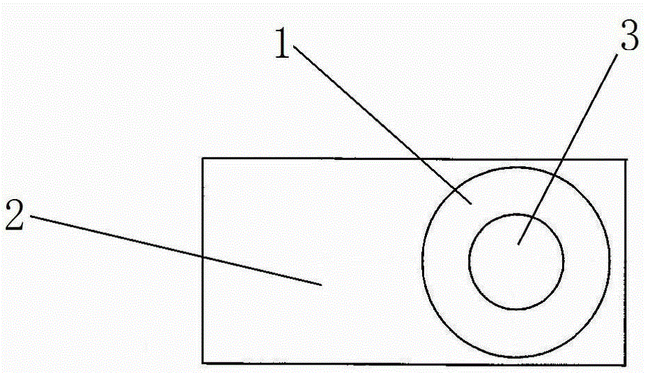
[0012] A dynamic rotating shaft seat of a viscosity machine, including a shaft seat and a round through hole, characterized in that the shaft seat is composed of a cylindrical seat 1 and a cuboid seat 2, and the cylindrical seat 1 is embraced by the rectangular parallelepiped seat 2; the cylindrical seat 1 exceeds The upper part of the cylindrical seat 1 on the top of the rectangular parallelepiped seat 2, the diameter of the outer circumference of the upper part of the cylindrical seat 1 is 6 mm, and the upper circular surface of the upper part of the cylindrical seat 1 is 4 mm from the top of the rectangular parallelepiped seat 2, and The lower part 7 of the cylindrical seat 1 beyond the bottom of the rectangular parallelepiped seat 2, the diameter of the outer circumference of the lower part 7 of the cylindrical seat 1 is 5mm, and the distance from the lower circular surf...


PUM

PropertyMeasurementUnit
diameteraaaaaaaaaa

Abstract

The invention discloses a rotating shaft seat of a viscosity meter. The rotating shaft seat comprises a shaft seat, wherein the shaft base is formed by connection of a cylindrical base and a cuboid base; the cylindrical base is enclosed by the cuboid base; an upper round surface of the upper part of the cylindrical base exceeds an upper surface of the cuboid base; a lower round surface of the lower part of the cylindrical base exceeds a lower surface of the cuboid base; the upper round surface of the upper part and the lower round surface of the lower part of the cylindrical base are concentric round surfaces; a circle center of the cylindrical base is 10 mm away from a left surface of the cuboid base and located between a front surface and a rear surface of the cuboid base; thicknesses of a front surface and a rear surface of a middle waist part of a connected body of the cuboid base and the cylindrical base are cut down by 1.5 mm respectively, front and rear grooves and a thin waist part are cut, a gap with the depth of 9 mm is dug leftwards from a right surface of the thin waist part, and a right gap of the waist part and a narrow waist part are formed; a round through hole drilled downwards in the upper round surface of the upper part of the cylindrical base is a through hole and communicated with the right gap of the waist part; a first threaded hole is drilled leftwards in a right surface of the cuboid base and communicated with the round through hole; and a second threaded hole drilled backwards in the front surface of the cuboid base is a through hole.

Description

technical field [0001] The invention relates to a dynamic shaft seat of a viscosity machine, in particular to an important part of a new instrument for measuring the viscous resistance of a liquid and the absolute viscosity of a liquid—a viscosity machine. Background technique [0002] Viscometer is widely used to measure the viscosity of oil, paint, food, medicine, adhesive and other fluids. Usually, it is required to measure the viscosity of various fluids in order to understand, grasp and improve the quality of the product, and to achieve this purpose, it is most necessary to complete the measurement with a viscosity machine with good performance. The existing viscosity machines are imported and expensive; some of the domestic ones have large errors, are inconvenient to use, and fail to achieve the purpose; our company has innovated and manufactured a new, practical and low-cost new type of viscometer in years of research and experiments. The viscosity machine has good q...

Claims


Application Information

Patent Timeline
Patent Type & Authority Patents(China)
IPC IPC(8): F16C35/00G01N9/00
Inventor 柯根祥
Owner PINGHU YONGGUANG MACHINERY PARTS
Why Eureka
Try Eureka