
Eureka
For R&D, Eureka makes reading and utilizing patents & technical documents easy.
Eureka AIR
Designed for self-driven R&D workflows. Generate viable solutions, solve complex R&D challenges, empower your innovation with AI.

Eureka Materials
Designed for material experts only. Revolutionize your material R&D, from search, analyze, to developing new materials.

TechResearch
Generate reliable direction feasibility study reports for your R&D in just a few steps.

TechSeek
Discover and master advanced knowledge NOW. Basics, ideas, possibilities, all at once.

TechMind
As an expert in R&D Theories, TechMind can generates customized viable solutions instantly.

TechRisk
Analyze your overall solution with one click, know your potential R&D risks in advance.

TechMonitor
Get weekly tech updates, stay abreast of the latest tech innovations and key insights.
Four-wheel-drive transfer case
A front-axle drive and rear-axle drive technology, which is applied to transmissions, transmission parts, gear transmissions, etc., can solve problems such as not being at the same level, providing power, and not being able to provide power
- Summary
- Abstract
- Description
- Claims
- Application Information
AI Technical Summary
Problems solved by technology
Method used
Image

Examples
Embodiment 1
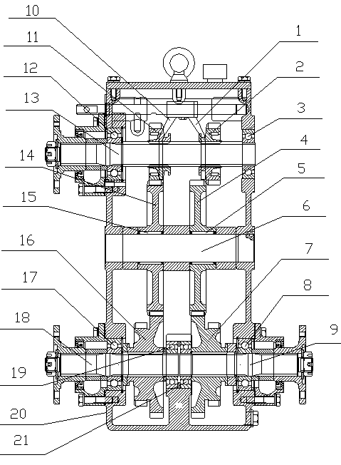
[0015] Such as figure 1 Shown: a kind of preferred embodiment of a kind of four-wheel drive transfer case of the present invention, comprises box body 20, front fork 10, rear fork 1, input shaft 13, intermediate shaft 6, front axle drive output shaft 18, rear Axle drive output shaft 9, front fork 10 and rear fork 1 are all installed on the top of casing 20, input shaft 13 is installed above casing 20 through first input shaft bearing 12 and second input shaft bearing 3, first input shaft The shaft bearing 12 and the second input shaft bearing 3 are both deep groove ball bearings, the left end of the input shaft 13 is the power input end, and the part of the input shaft 13 in the box body 20 is sequentially installed with the first shift gear 11 from left to right , the second shift gear 2, the first shift gear 11, and the second shift gear 2 can slide axially along the input shaft 13; the intermediate shaft 6 is fixed on the middle part of the casing 20, and the intermediate s...
Embodiment 2
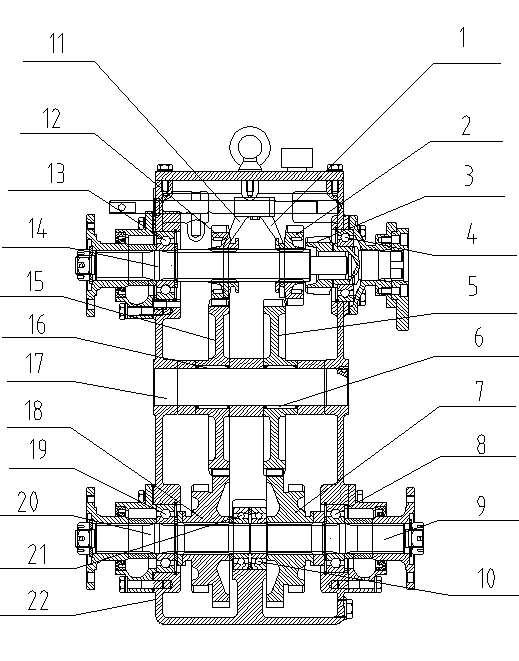
[0017] Such as figure 2 Shown: Another preferred embodiment of a four-wheel drive transfer case of the present invention, including a box body 22, a front fork 11, a rear fork 1, an input shaft 14, an oil pump drive 3, an intermediate shaft 17, and a front axle drive Output shaft 20, rear axle drive output shaft 9, front fork 11 is installed on the top of casing 22, rear fork 1 is installed on top of casing 22, input shaft 14 is installed on the top of casing 22 through input shaft bearing 13, input shaft The bearing 13 is a deep groove ball bearing, the left end of the input shaft 14 is the power input end, and the part of the input shaft 14 in the box body 22 is sequentially installed with the first shift gear 12, the second shift gear 2, and the second shift gear 2 from left to right. Both the first shift gear 12 and the second shift gear 2 can slide axially along the input shaft 14; the oil pump drive 3 is installed on the upper right side of the casing 22 through the oil...
PUM
 Abstract
Description
Claims
Application Information
 - R&D Engineer
- R&D Manager
- IP Professional
- Industry Leading Data Capabilities
- Powerful AI technology
- Patent DNA Extraction
Browse by: Latest US Patents, China's latest patents, Technical Efficacy Thesaurus, Application Domain, Technology Topic, Popular Technical Reports.
© 2024 PatSnap. All rights reserved.Legal|Privacy policy|Modern Slavery Act Transparency Statement|Sitemap|About US| Contact US: help@patsnap.com