
Broadband circular polarization high-gain low-profile microstrip slot antenna capable of loading hyper-surface

A technology of microstrip slots and circular polarization, which is applied in the direction of slot antennas, antennas, antenna grounding devices, etc., can solve the problems of high profile, complex feeding structure, narrow polarization bandwidth, etc., and achieve low profile, high gain, and processing convenient effect

Inactive Publication Date: 2016-08-17
UNIV OF ELECTRONIC SCI & TECH OF CHINA
View PDF2 Cites 29 Cited by
  • Summary
  • Abstract
  • Description
  • Claims
  • Application Information

AI Technical Summary

Problems solved by technology

[0003] The purpose of the present invention is to overcome the shortcomings of the existing microstrip slot antenna technology such as narrow polarization bandwidth, high profile, and complex feeding structure, and propose a microstrip slot antenna loaded with metasurfaces, which can effectively realize circular polarization , wideband, high gain and low profile working loaded metasurface broadband circularly polarized high gain low profile microstrip slot antenna

Method used


Image

  • Broadband circular polarization high-gain low-profile microstrip slot antenna capable of loading hyper-surface
  • Broadband circular polarization high-gain low-profile microstrip slot antenna capable of loading hyper-surface
  • Broadband circular polarization high-gain low-profile microstrip slot antenna capable of loading hyper-surface

Examples


Embodiment Construction

[0019] The preferred embodiments of the present invention will be described below in conjunction with the accompanying drawings. It should be understood that the preferred embodiments described here are only used to illustrate and explain the present invention, and are not intended to limit the present invention.

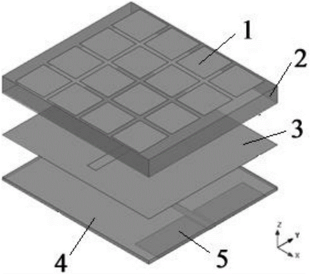
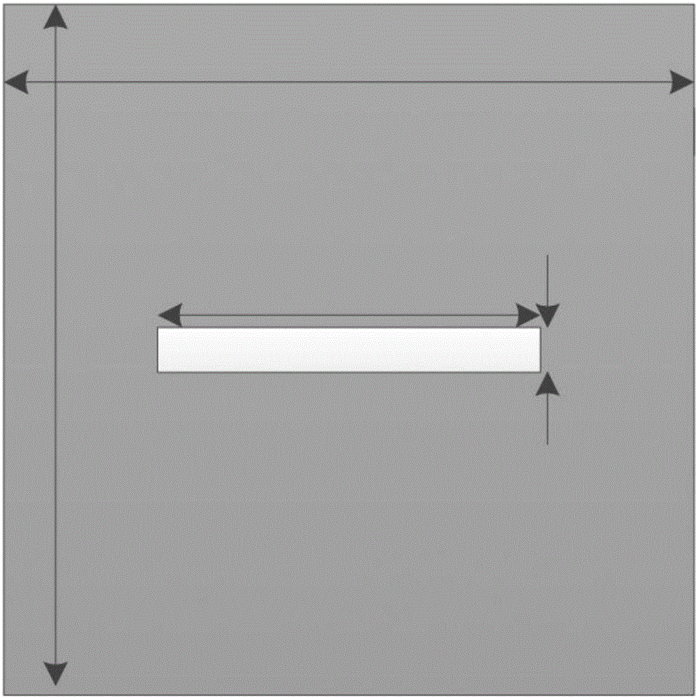
[0020] Such as figure 1 As shown, a wide-band circularly polarized high-gain low-profile microstrip slot antenna loaded with a metasurface can realize circularly polarized radiation in the 5.1-6.3GHz frequency band. A metal copper ground plate 3 with gaps and a lower dielectric substrate 4 , the upper surface of the upper dielectric substrate 2 is provided with a metal patch group 1 , and the lower surface of the lower dielectric substrate 4 is provided with a coplanar waveguide feeding structure 5 .

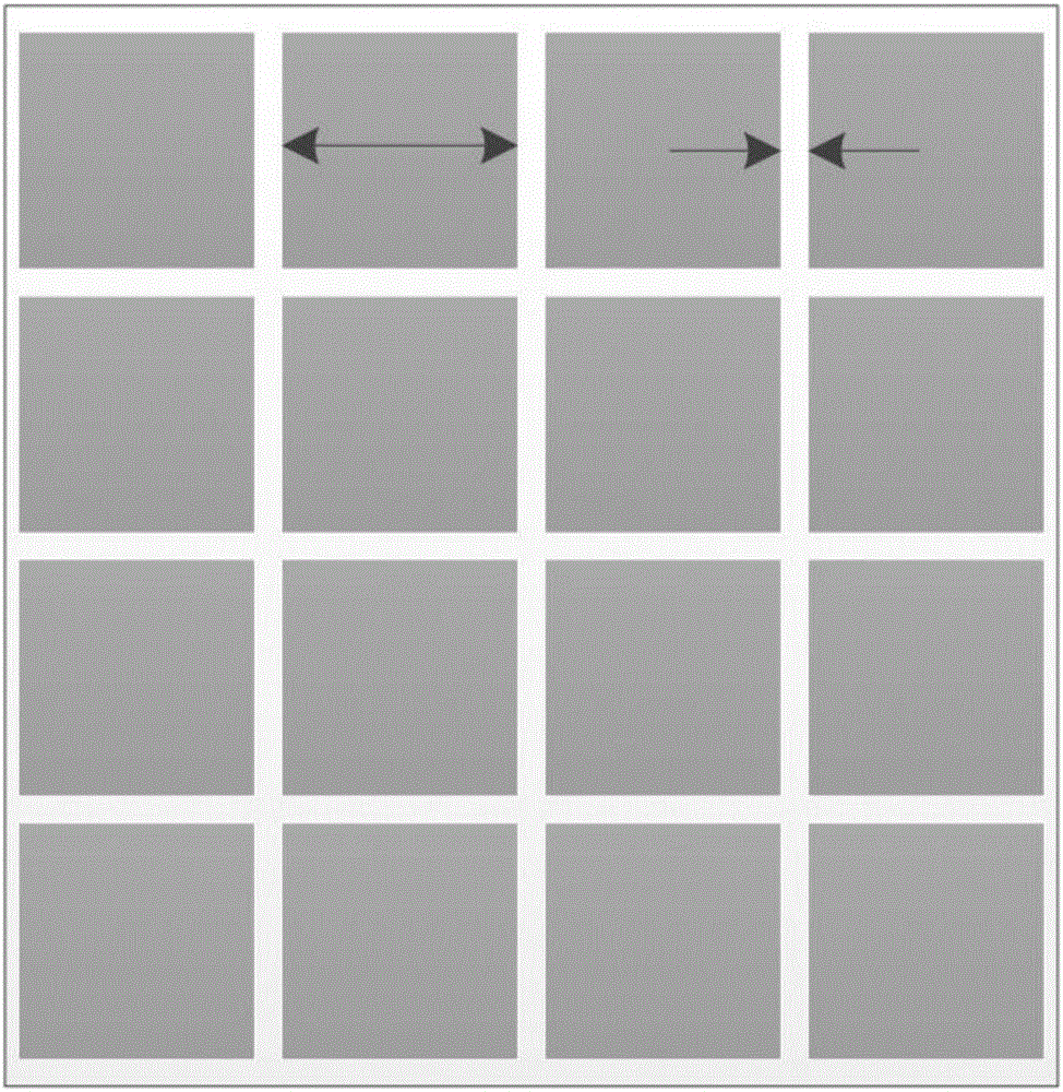
[0021] Such as figure 2 As shown, the metal patch group 1 is composed of 16 square chamfered metal patches arranged in a 4×4 array, the side length of the metal pat...


PUM

PropertyMeasurementUnit
Side length sizeaaaaaaaaaa
Thicknessaaaaaaaaaa
Widthaaaaaaaaaa

Abstract

The invention discloses a broadband circular polarization high-gain low-profile micro-strip slot antenna capable of loading a hyper-surface; the broadband circular polarization high-gain low-profile micro-strip slot antenna can realize circular polarization radiation at a frequency band being 5.1-6.3GHz. The broadband circular polarization high-gain low-profile microstrip slot antenna sequencially comprises an upper-layer dielectric substrate (2), a metal copper grounding plate (3) with a seam, and a lower-layer dielectric substrate (4) which are in tight contact from top to bottom, wherein a metal paster set (1) is arranged on the upper surface of the upper-layer dielectric substrate (2); the lower surface of the lower-layer dielectric substrate (4) is provided with a coplanar waveguide feeding structure (5). According to the broadband circular polarization high-gain low-profile microstrip slot antenna, the metal paster set and the upper-layer dielectric substrate form a hyper-surface structure, so that conversion from linear polarized waves to circular polarized waves is realized; the coplanar waveguide feeding structure and the metal copper grounding plate jointly form a coplanar waveguide with a floor for feeding to the antenna from a signal conduction band. A hyper-surface loading technology is adopted based on the micro-band seam antenna, and the coplanar waveguide is utilized for feeding, so that the antenna has the advantages of circular polarization characteristic, high gain and low profile within a broadband, is simple in structure, and is convenient to process.

Description

technical field [0001] The invention relates to an antenna used in the technical field of communication, in particular to a metasurface-loaded broadband circularly polarized high-gain low-profile slot microstrip antenna. Background technique [0002] The radio frequency identification system consists of a reader antenna, an electronic tag and a computer communication network. The reader antenna emits electromagnetic energy to activate the tag to realize data transmission and issue instructions to the tag, and also to receive information from the tag. Since the tag antenna is generally linearly polarized, and the gain is relatively low, in order to be able to read the electronic tag information with different polarization characteristics and realize the maximum signal energy transmission between the reader and the tag as much as possible, the reader antenna is required It has the characteristics of circular polarization and high gain. In recent years, researchers have propos...

Claims


Application Information

Patent Timeline
IPC IPC(8): H01Q1/38H01Q1/48H01Q13/10H01Q13/08
CPCH01Q1/38H01Q1/48H01Q13/08H01Q13/106
Inventor 文光俊杨力黄勇军李建
Owner UNIV OF ELECTRONIC SCI & TECH OF CHINA
Learn More