Sealed oil catch for main shaft of wind driven generator

A wind turbine and main shaft sealing technology is applied in the field of sealing oil shields, which can solve the problems affecting the safe operation and civilized production of wind turbines, poor sealing effect, increased grease leakage, etc., and achieves simple structure and prevents grease leakage. , The effect of not increasing the sealing gap

Inactive Publication Date: 2014-04-16
秦皇岛华宇通电力科技有限公司
View PDF7 Cites 2 Cited by
  • Summary
  • Abstract
  • Description
  • Claims
  • Application Information

AI Technical Summary

Problems solved by technology

However, in practical applications, with the continuous operation of the wind turbine, the sealing gap between the V-shaped sealing rubber ring and the rotating shaft is increasing, and the leakage of grease is also increasing, and the sealing effect is getting worse and worse, seriously affecting Safe operation and civilized production of wind turbines

Method used


Image

  • Sealed oil catch for main shaft of wind driven generator
  • Sealed oil catch for main shaft of wind driven generator
  • Sealed oil catch for main shaft of wind driven generator

Examples


Embodiment 1

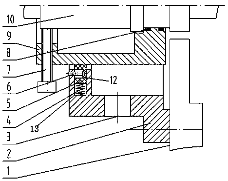
[0019] like figure 1 As shown, the wind turbine main shaft sealing oil shield of this embodiment includes a static ring 2 installed on the engine casing 1, a moving ring 9 fixed on the rotating shaft 10 and rotating with the rotating shaft 10; the moving ring 9 and the static ring 2 are provided with a floating sealing ring 5, the inner surface of the static ring 2 is provided with an annular groove 13, the floating sealing ring 5 is located in the annular groove 13, and the bottom of the annular groove 13 A spring 4 is arranged between the floating seal ring 5 .

Embodiment 2

[0021] like figure 1 As shown, the basic structure and function of the seal oil shield of the main shaft of the wind power generator in this embodiment are the same as those in Embodiment 1, the difference is that the moving ring 9 is provided with an adjusting screw 7, and the end of the adjusting screw 7 is on the top On the outer surface of the rotating shaft 10 , the adjusting screw 7 is screwed with the moving ring 9 to adjust the concentricity between the moving ring 9 and the rotating shaft 10 . Two O-rings 8 are arranged between the moving ring 9 and the rotating shaft 10 .

Embodiment 3

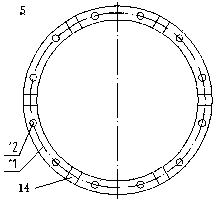
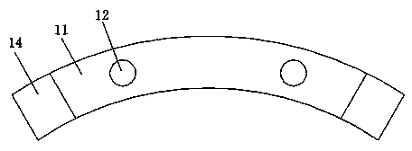
[0023] like figure 1 As shown, the basic structure and function of the wind turbine main shaft sealing oil shield of this embodiment are the same as those of Embodiments 1 and 2, the difference is that the outer surface of the floating sealing ring 5 is provided with a plurality of circular grooves 12, The outer surface of the annular groove 13 of the static ring 2 is provided with a plurality of pin holes, the pin holes are correspondingly arranged with the circular groove 12, and the positioning pin 6 is arranged in the pin hole, and the positioning pin 6 is inserted into the circular groove 12. shaped groove 12.


PUM


Abstract

The invention provides a sealed oil catch for a main shaft of a wind driven generator, which is better in sealing effect and simple in structure. The sealed oil catch comprises a static ring, and a mobile ring, wherein the static ring is arranged on an engine shell, and the mobile ring is fixedly arranged on a rotating shaft and rotates together with the rotating shaft; a floating seal ring is arranged between the mobile ring and the static ring, a circular groove is formed in the inner surface of the static ring, the floating seal ring is positioned in the circular groove, and a spring is arranged between the bottom of the circular groove and the floating seal ring. By adopting the floating seal ring, the sealed oil catch for the main shaft of the wind driven generator has elasticity so as to adapt to the rotation of the rotating shaft and ensure no wear after being used for a long time, and the sealing clearance is not increased, so that the purpose of effectively preventing the leakage of lubricating oil, as well as the sealing purpose can be achieved, and the sealed oil catch for the main shaft of the wind driven generator is simple in structure, low in cost, and suitable for wide application.

Description

technical field [0001] The invention relates to a sealing oil shield, in particular to a sealing oil shield for a main shaft of a wind power generator. Background technique [0002] In recent years, with the development of new energy sources, the market of clean energy has developed rapidly. Compared with other energy sources, wind power has the characteristics of cleanliness and environmental protection. With the large-scale and systematic development of wind turbines, it has become an inevitable technical problem in the design and manufacture of wind turbines to effectively solve the grease leakage of the main shaft thrust bearing during the operation of wind turbines. The wind turbine main shaft sealing oil shield is an important part of the wind turbine, and its function is to seal the grease leakage at the wind turbine main shaft bearing. Its sealing effect directly determines the safety, economy and daily maintenance workload of wind turbine operation. The traditiona...

Claims


Application Information

Patent Timeline
IPC IPC(8): F16J15/16F03D11/00
CPCY02E10/722Y02P70/50
Inventor 柯福高俊华
Owner 秦皇岛华宇通电力科技有限公司
Why Eureka
Try Eureka