Motor installation plate of viscosity meter

A motor mounting plate, viscosity machine technology, applied in the direction of measuring devices, flow characteristics, instruments, etc., can solve problems such as unstable operation of the viscosity machine, affecting product quality, unreasonable structure, etc., to achieve reasonable structure, meet production needs, and design correct effect

Inactive Publication Date: 2014-04-16
PINGHU YONGGUANG MACHINERY PARTS
View PDF4 Cites 3 Cited by
  • Summary
  • Abstract
  • Description
  • Claims
  • Application Information

AI Technical Summary

Problems solved by technology

[0004] In order to overcome defects such as unstable operation, inaccurate measurement, large errors, and affecting product quality caused by the wrong design and unreasonable structure of the motor mounting plate of the ordinary viscosity machine; the invention provides a motor mounting plate of the viscosity machine, The motor mounting plate of the viscosity machine is an important part of the viscosity machine. The design is correct and the structure is reasonable, which can make the viscosity machine work stably, ensure accurate measurement, stable performance, high precision, and detection in place

Method used


Image

  • Motor installation plate of viscosity meter
  • Motor installation plate of viscosity meter
  • Motor installation plate of viscosity meter

Examples


Embodiment Construction

[0015] The present invention will be further described below in conjunction with accompanying drawing:

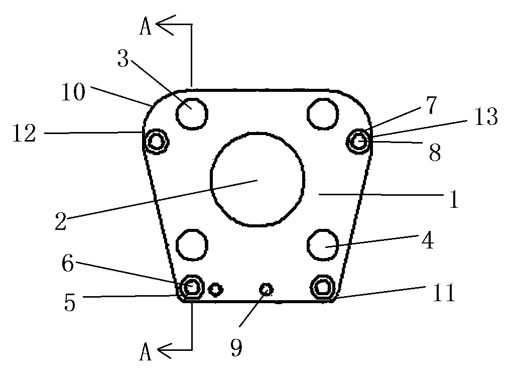
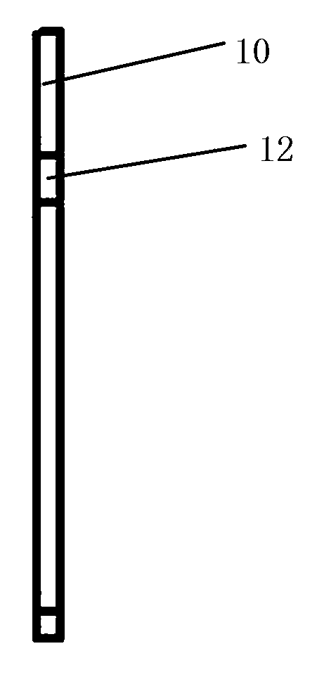
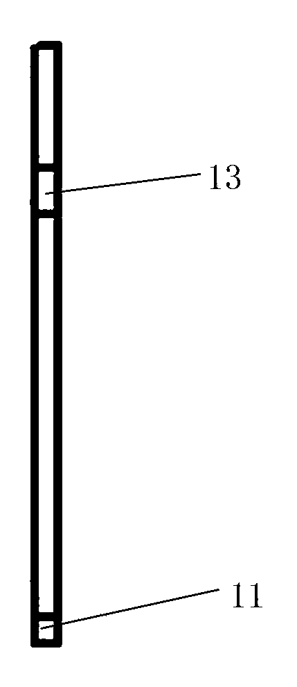
[0016] A motor mounting plate for a viscosity machine, comprising a plate body and a through hole in the middle, characterized in that the upper and lower sides of the plate body 1 are horizontal planes, the thickness of the plate body 1 is 2mm, and the height of the upper and lower sides of the plate body 1 is 50mm; The left side of the plate body 1 is composed of a left longitudinal surface 12 and a left oblique surface, and the height of the upper and lower sides of the left longitudinal surface 12 is 4 mm; the right side of the plate body 1 is composed of a right longitudinal surface 13 and a right oblique surface, and the right longitudinal surface The height of the top and bottom of 13 is 4mm; there is an upper left fillet 10 connected between the top of the plate body 1 and the left side of the plate body 1, and the radius of the upper left fillet 10 is 10mm; the bott...


PUM

PropertyMeasurementUnit
Thicknessaaaaaaaaaa
Heightaaaaaaaaaa
Radiusaaaaaaaaaa

Abstract

The invention discloses a motor installation plate of a viscosity meter. The motor installation plate comprises a plate body and a middle through hole. The motor installation plate is characterized in that upper and lower surfaces of the plate body are horizontal surfaces; the middle through hole is dug backwards in the middle of a front surface of the plate body; an upper left installation hole is dug in the upper left part of the front surface of the plate body, a lower left installation hole is dug in the lower left part, an upper right installation hole is dug in the upper right part, and a lower right installation hole is dug in the lower right part; a first round hole is dug backwards on the left side of the upper left installation hole; a second round hole is dug backwards on the right side of the upper right installation hole; a third round hole is dug backwards in the lower left part of the front surface of the plate body; a fourth round hole is dug backwards in the lower right part of the front surface of the plate body; a fifth round hole, a sixth round hole, a seventh round hole and an eighth round hole are correspondingly dug backwards in rear round hole surfaces of the first round hole, the second round hole, the third round hole and the fourth round hole respectively; a left threaded hole is drilled backwards on the right side of the third round hole and in the lower part of the front surface of the plate body; and a right threaded hole is drilled backwards on the right side of the left threaded hole.

Description

[0001] technical field [0002] The invention relates to a motor mounting plate of a viscosity machine, in particular to an important part of a new instrument for measuring the viscous resistance of a liquid and the absolute viscosity of a liquid—a viscosity machine. Background technique [0003] Viscometer is widely used to measure the viscosity of oil, paint, food, medicine, adhesive and other fluids. Usually, it is required to measure the viscosity of various fluids in order to understand, grasp and improve the quality of the product, and to achieve this purpose, it is most necessary to complete the measurement with a viscosity machine with good performance. The existing viscosity machines are imported and expensive; some of the domestic ones have large errors, are inconvenient to use, and fail to achieve the purpose; our company has innovated and manufactured a new, practical and low-cost new type of viscometer in years of research and experiments. The viscosity mach...

Claims


Application Information

Patent Timeline
IPC IPC(8): G01N11/00
Inventor 柯根祥
Owner PINGHU YONGGUANG MACHINERY PARTS
Why Eureka
Try Eureka