Camera protection circuit

A technology for protecting circuits and cameras, applied in the field of cameras, can solve the problems of unstable current limiting, low accuracy, and camera shutdown, etc., to achieve the effect of adjustable current and high accuracy

Inactive Publication Date: 2014-04-16
CHENGDU HONGSHAN TECH
View PDF4 Cites 1 Cited by
  • Summary
  • Abstract
  • Description
  • Claims
  • Application Information

AI Technical Summary

Problems solved by technology

As a powered device, when the switching power supply starts to work, a surge circuit will be generated. The unlimited large current will cause the port voltage to drop rapidly. switching, affecting the stability of the work
In order to avoid this situation, most of the structure of the circuit limiting circuit is used to connect a small sampling tube in parallel to the output power tube. The sampling accuracy is not high, and the current limiting is unstable.

Method used


Image

  • Camera protection circuit

Examples


Embodiment

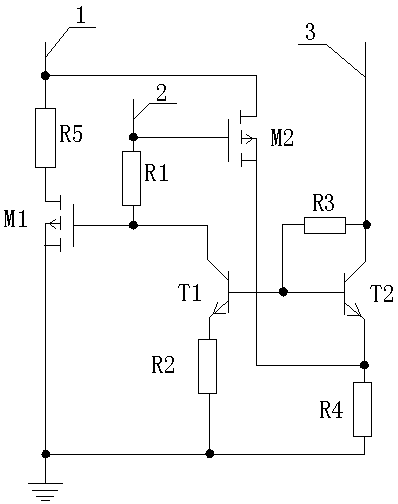
[0016] Such as figure 1 A kind of camera protection circuit shown, it comprises port A, port B and port C, and described port A is connected on the drain of field effect transistor M2, and described port A is connected with the drain of field effect transistor M1 through resistance R5 The source of the field effect transistor M1 is grounded, the port B is connected to the gate of the field effect transistor M2, and the port B is connected to the gate of the field effect transistor M1 and the transistor T1 through the resistor R1 On the collector of the triode T1, the emitter of the triode T1 is grounded through the resistor R2, the base of the triode T1 is connected to the base of the triode T2, and the port C is connected to the collector of the triode T2. A resistor R3 is connected between the collector and the base of the transistor T2, the emitter of the transistor T2 is connected to the ground through the resistor R4, and the source of the field effect transistor M2 is co...


PUM


Abstract

The invention discloses a camera protection circuit. The camera protection circuit comprises a port A, a port B and a port C. The port A is connected on a drain of a field-effect tube M2, the port A is connected with a drain of a field-effect tube M1 through a resistor R5, a source of the field-effect tube M1 is grounded, the port B is connected to a grid of the field-effect tube M2, the port B is connected to a grid of the field-effect tube M1 and a collector of an audion T1 through resistors R1 at the same time, an emitter of the audion T1 is grounded through a resistor R2, a base of the audion T1 is connected to a base of an audion T2, the port C is connected to a collector of an audion T2, a resistor R3 is connected between the collector of the audion T2 and the base of the audion T2, an emitter of the audion T2 is grounded through a resistor R4 and a source of the field-effect tube M2 is connected to an emitter of the audion T2. The camera protection circuit has the advantages of being high in sampling precision and adjustable in current.

Description

technical field [0001] The invention relates to the field of cameras, and more specifically relates to a camera protection circuit. Background technique [0002] As a video input device, the camera is widely used in various aspects, such as video conferencing, remote monitoring, and emotional communication. As a powered device, when the switching power supply starts to work, a surge circuit will be generated. The unlimited large current will cause the port voltage to drop rapidly. The switching will affect the stability of the work. In order to avoid the occurrence of this situation, most of them adopt the structure of circuit limiting circuit to connect a small sampling tube in parallel to the output power tube, the sampling accuracy is not high, and the current limiting is unstable. Contents of the invention [0003] The invention provides a camera protection circuit with high sampling precision and adjustable current. [0004] In order to solve the above-mentioned te...

Claims


Application Information

Patent Timeline
Patent Type & Authority Applications(China)
IPC IPC(8): G05F1/56
Inventor 黄友华
Owner CHENGDU HONGSHAN TECH
Why Eureka
Try Eureka