Imaging screen configuring method of splicing type display screen

A graphic and display technology, which is applied in the direction of static indicators, instruments, identification devices, etc., can solve problems such as inability to operate LED cabinet screens, complex configuration methods, and high-level staff, and achieve intuitive screen configuration operations.

Active Publication Date: 2014-04-16
XIAN NOVASTAR TECH
View PDF4 Cites 34 Cited by
  • Summary
  • Abstract
  • Description
  • Claims
  • Application Information

AI Technical Summary

Problems solved by technology

But this method has the following problems: (1) It cannot provide a fast splicing method, and it has high requirements for the staff, who need to understand the above layout files and driver files; (2) The receiving card configured for each L

Method used


Image

  • Imaging screen configuring method of splicing type display screen
  • Imaging screen configuring method of splicing type display screen
  • Imaging screen configuring method of splicing type display screen

Examples


no. 1 example

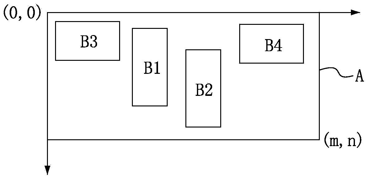
[0020] figure 1 with Figure 2A-2B It is a schematic diagram of part of the process of a graphical screen arrangement method for spliced ​​display screens according to the first embodiment of the present invention. In the first embodiment, the spliced ​​display screen is, for example, an LED display screen. As far as a single LED display screen is concerned, it usually includes multiple LED boxes, and a single LED box includes a video control card and one or more LED light boards carried by the video control card; LED driver chips and multiple LED chips or lamps on the board, these LED chips or lamps can be LED chips or lamps of one color, LED chips or lamps of two colors, LED chips or lamps of three colors, or even more LED chips or lamps of various colors, the bright and dark states of these LED chips or lamps are controlled by the LED driver chip. In addition, the video control card can be a receiving card, which can obtain the display content from the video output port ...

no. 2 example

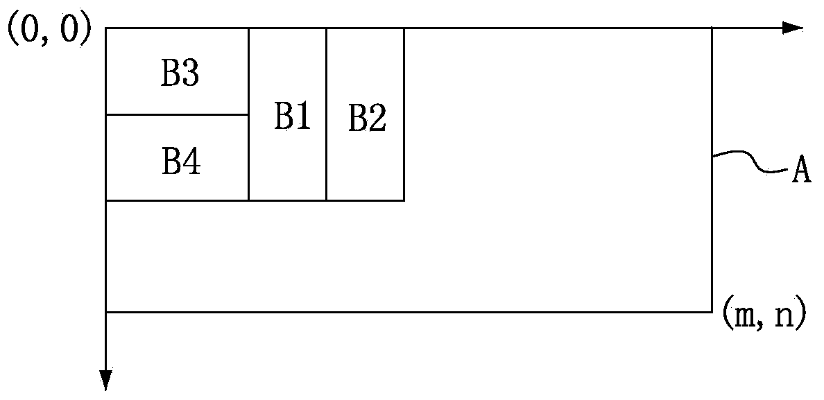
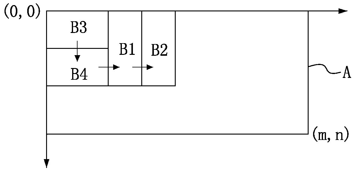
[0028] image 3 with Figures 4A-4C It is a schematic diagram of part of the process of a method for graphically arranging spliced ​​display screens according to the second embodiment of the present invention. In the second embodiment, the spliced ​​display screen is, for example, an LED display screen. As far as a single LED display screen is concerned, it usually includes multiple LED boxes, and a single LED box includes a video control card and one or more LED light boards carried by the video control card; LED driver chips and multiple LED chips or lamps on the board, these LED chips or lamps can be LED chips or lamps of one color, LED chips or lamps of two colors, LED chips or lamps of three colors, or even more LED chips or lamps of various colors, the bright and dark states of these LED chips or lamps are controlled by the LED driver chip. In addition, the video control card can be a receiving card, which can obtain the display content from the video output port (suc...


PUM


Abstract

The invention relates to an imaging screen configuring method of a splicing type display screen. The method comprises the steps that (a) configuration parameters comprising the resolution ratios of a plurality of physical splicing units are obtained; (b) a plurality of imaging splicing units corresponding to the physical splicing units respectively are generated according to the obtained configuration parameters, wherein the imaging splicing units with different shape sizes are generated correspondingly through different resolution ratios; (c) the multiple imaging splicing units are arrayed in one splicing zone responding to user operation, and the multiple imaging splicing units which are arrayed in the splicing zone are subjected to wiring; and (d) according to the positions, the shape sizes and wiring of the multiple imaging splicing units in the splicing zone, the video display coordinate and wiring relationship of the multiple physical splicing units is obtained, and accordingly display screen configuration information is generated. According to the method, the splicing units are represented in an imaging mode, the imaging splicing units with different shape sizes are generated correspondingly through different resolution ratios, and accordingly screen configuring operation is visual, quick and convenient.

Description

technical field [0001] The invention relates to the field of display technology, in particular to a graphical screen distribution method for spliced ​​display screens. Background technique [0002] LED (Light Emitting Diode, light-emitting diode) displays are more and more widely used, and the on-site splicing and screen matching of large screens are becoming more and more complicated. In order to improve the splicing efficiency of the LED cabinet of the on-site display, and In order to improve the parameter acquisition efficiency, many screen matching devices and computer-aided software have appeared. [0003] However, in the existing screen distribution devices and computer-aided software, computer-aided software is usually used to simulate the layout files and corresponding drive files for the splicing of display LED cabinets, and the staff produce LED boxes according to the layout files and drive files. Body and splicing display. But this method has the following probl...

Claims


Application Information

Patent Timeline
IPC IPC(8): G09F9/33G09G3/32
Inventor 陆威赵星梅
Owner XIAN NOVASTAR TECH
Why Eureka
Try Eureka