Pressure regulator

A pressure regulator and regulator technology, applied in the direction of fluid pressure control without auxiliary power, etc., can solve the problem of unable to prevent the adjustment condition, and achieve the effect of eliminating unqualified

Active Publication Date: 2014-04-16
МЄЛЬНІКОВ ПАВЄЛ ЕДУАРДОВІЧ
View PDF8 Cites 3 Cited by
  • Summary
  • Abstract
  • Description
  • Claims
  • Application Information

AI Technical Summary

Problems solved by technology

The structure of the regulator has been described above, but it does not prevent the occurrence of non-compliant regulation conditions

Method used


Image

  • Pressure regulator
  • Pressure regulator

Examples


Embodiment Construction

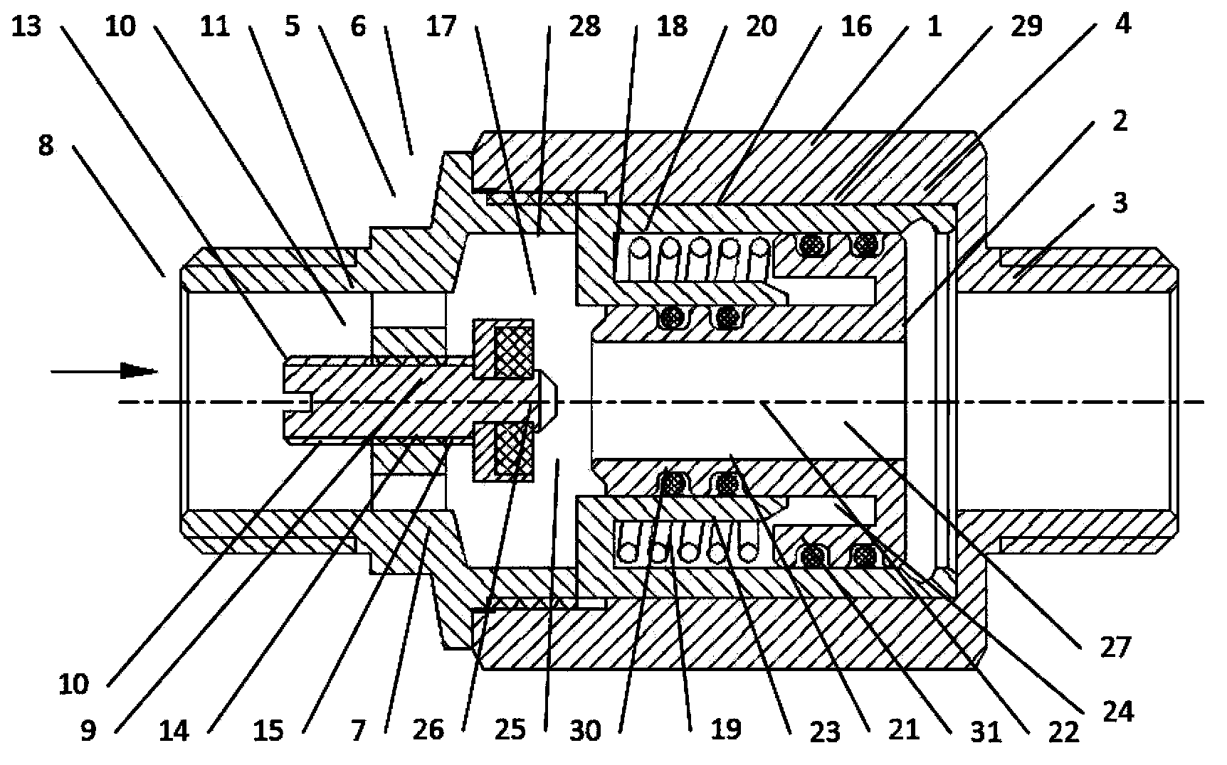
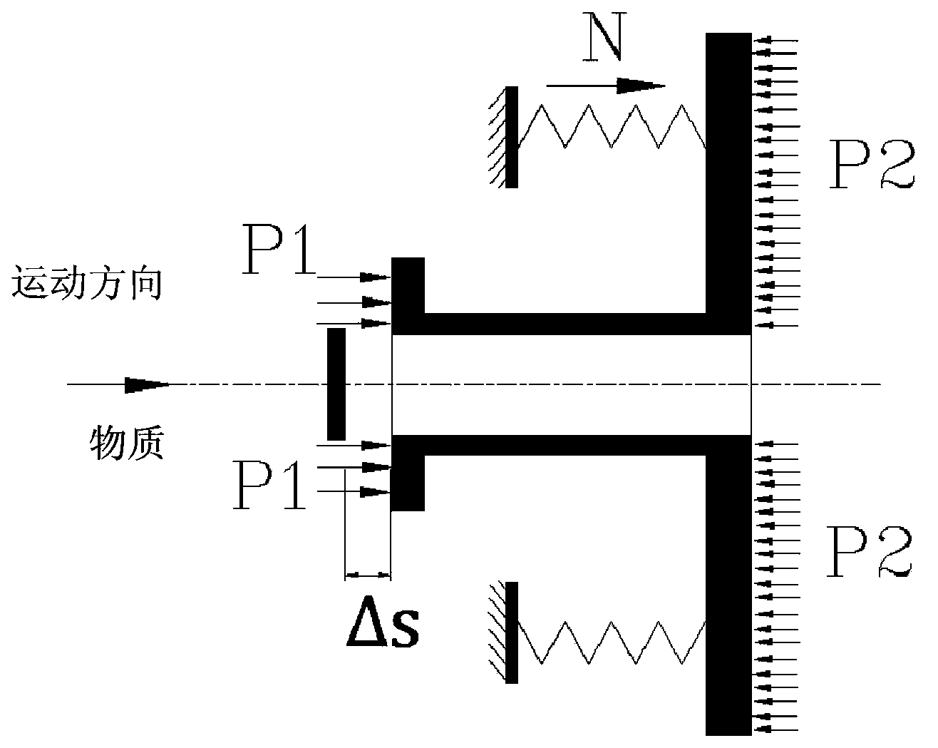
[0031] A specific exemplary pressure regulator provides the possibility to practice this invention. The diagram below is a schematic representation of the pressure regulator. figure 1 is a longitudinal sectional view of the pressure regulator, figure 2 Schematic diagram of the efficacy of its regulatory components.

[0032] The pressure regulator comprises a housing 1 . The housing 1 is provided with a cavity 2 and a member 3 for connecting a transport pipeline from a first end 4 (this is not shown in the schematic diagram). The insert 5 is closely connected with the shell 1 and is located at the second end 6 of the shell 1 , and has a cavity 7 and a member 8 thereon for connecting the transportation pipeline with the other side of the shell 1 . The tight connection between the housing 1 and the insert 5 mainly depends on the threaded engagement between them.

[0033] The valve 9 is mounted inside the cavity 7 of the insert 5 , and can move longitudinally or be fixed in p...


PUM


Abstract

The technical result of the invention is that of increasing the range of means for regulating the pressure of a liquid or gaseous medium undergoing transport, and providing automatic downstream pressure regulation within a pre-set range while preventing unauthorized access to change the set parameters.; The pressure regulator comprises a housing (1) provided with a through cavity (2) and a member (3) at the first end (4) for connection to a pipe, a plug (5) rigidly connected to the housing (1) at the second end (6) and provided with a through cavity (7) and a member (8) for connection to the pipe on the opposite side of the housing (1), a collar (16) situated inside the cavity (2) of the housing (1) and rigidly fastened thereto and also being provided with a through cavity (17), a valve (9) mounted in the plug (5) such as to be capable of longitudinal movement and of maintaining a fixed position to allow the passage of the transported medium through the through cavity (7) of the plug (5), a sleeve (21) provided with a through cavity (22) and mounted in the through cavity (17) of the collar (16); such as to be capable of longitudinal movement and of interacting via one end surface (26) with the valve (9) in order to prevent the movement of the transported medium, and a compression spring (20) situated in the collar (16) such as to be capable of interacting with the sleeve (21), with compression in the direction of the movement of the sleeve (21) towards the valve (9). The area of projection onto a transverse plane of the end surface (26) of the sleeve (21) which is free to interact with the transported medium at the plug (5) end is less than the area of projection onto a transverse plane of the end surface (27) of the sleeve (21) which is free to interact with the transported medium at the first end (4) of the housing (1).

Description

technical field [0001] The invention belongs to the field of construction, and specifically relates to a pressure regulator (regulator), whose main function is to reduce the pressure of transported substances in the entire system, which not only includes reducing the impact of transported substances on hot and cold water supply equipment, water heating devices , The pressure generated by the entire network system of the pneumatic compression device, but also includes the reduction of the pressure generated by the transportation material on the natural gas and other liquid transportation technology pipelines. The pressure of the pressure regulator is mainly determined by the tuning pressure at the outlet, regardless of sudden changes in the pressure in the entire network system, or in a static mode (the adjusted pressure of the pressure regulator is lower than the tuning pressure). Background technique [0002] This known pressure regulator is a longitudinal through-chamber p...

Claims


Application Information

Patent Timeline
IPC IPC(8): G05D16/08
Inventor 帕沃·艾多德维奇·麦呢科夫
Owner МЄЛЬНІКОВ ПАВЄЛ ЕДУАРДОВІЧ
Why Eureka
Try Eureka