A flattening mold with cooling circulation system

A circulation system and mold technology, applied in the field of stamping molds, can solve the problems of punches and products heating, the service life and production efficiency of molds and parts, and the difficulty of maintenance, so as to reduce the probability of water leakage and failure, and reduce heat Deformation and springback effect, the effect of improving the stability of flattened thickness

Active Publication Date: 2017-01-18
惠州安特科技工业有限公司
View PDF11 Cites 0 Cited by
  • Summary
  • Abstract
  • Description
  • Claims
  • Application Information

AI Technical Summary

Problems solved by technology

[0002] On stamping molds such as flattening dies, due to the large amount of flattening of the material, the punch and the product will heat up severely, which will cause the flattened thickness to be unstable.
By cooling the mold, the mold can be kept at an appropriate temperature, which is beneficial to ensure the quality of the molded product and improve the efficiency of mold molding. The traditional cooling method is to use gas cooling technology to process air holes and air on the mold. The cooling gas is sprayed onto the surface of the workpiece to realize the gas quenching effect on the workpiece. This type of mold has a complex structure and high cost, and there are many inconveniences in the preparation, storage, and transportation of the cooling gas during use.
Another method is water cooling technology. A water tank is set in the die seat, and the quenching of the parts is realized by directly contacting the cooling water with the mold components. This method is prone to water leakage, because both the mold and the parts belong to metal tools. , if the water leakage is not cleaned up in time, the service life and production efficiency of the mold and parts will be greatly reduced, and the maintenance will be difficult

Method used


Image

  • A flattening mold with cooling circulation system
  • A flattening mold with cooling circulation system

Examples


Embodiment Construction

[0017] In order to allow those skilled in the art to better understand the technical solutions of the present invention, the present invention will be further described below in conjunction with the accompanying drawings.

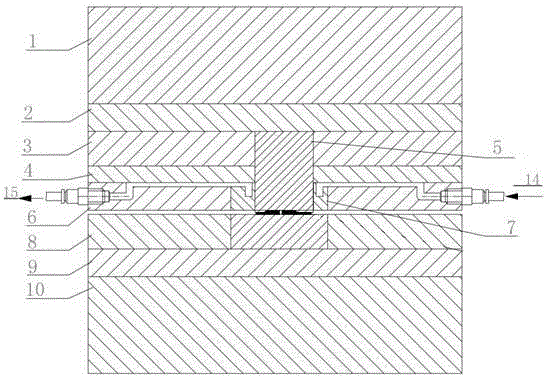
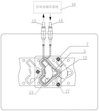
[0018] Such as figure 1 As shown, a flattening die with a cooling circulation system includes an upper die base 1 connected to a slide on the punch press, a lower die base 10 installed on the punch workbench, a punch fixing plate 3 below the upper die base 1, Punch fixing plate backing plate 2 between upper die base 1 and punch fixing plate 3, unloading plate 6 under punch fixing plate 3, unloading plate pad between punch fixing plate 3 and unloading plate 6 Plate 4, the flat punch 5 fixed on the punch fixing plate 3, the concave template 8 above the lower mold base 10 and the concave template backing plate 9 between the concave template 8 and the lower mold base 10, the discharge plate 6 A discharge plate insert 7 is provided inside, and a water circulati...


PUM


Abstract

The invention discloses a flattening mould with a cooling cycle system. The flattening mould with the cooling cycle system comprises an upper mould holder connected with a punch press upper slider, a lower mould holder mounted on a punch press workbench, a punch fixing plate mounted under the upper mould holder, an unloading plate mounted under the punch fixing plate, a flattening punch fixed onto the punch fixing plate, and a cavity mould plate above the lower mould holder. The flattening mould with the cooling cycle system is characterized in that the unloading plate is provided with an unloading insert, and a water circulation system is formed inside the insert and connected with a cooling water circulation system. The flattening mould with the cooling cycle system can rapidly cool the mould and the punch through the build-in cooling cycle system to avoid uneven flattening thickness due to heating of the punch; the water circulation channel is arranged on the unloading plate without direct contact with the mould, thereby reducing the possibility of water leakage and fault of the mould, facilitating disassembly and cleaning and greatly prolonging the service life of the mould.

Description

technical field [0001] The invention relates to a stamping die, in particular to a flattening die with a cooling circulation system. Background technique [0002] On stamping molds such as flattening dies, due to the large amount of flattening of the material, the punch and the product will heat up severely, which will cause the flattened thickness to be unstable. By cooling the mold, the mold can be kept at an appropriate temperature, which is beneficial to ensure the quality of the molded product and improve the efficiency of mold molding. The traditional cooling method is to use gas cooling technology to process air holes and air on the mold. The cooling gas is sprayed onto the surface of the workpiece to realize the gas quenching effect on the workpiece. This type of mold has a complex structure and high cost, and there are many inconveniences in the preparation, storage, and transportation of the cooling gas during use. Another method is water cooling technology. A wat...

Claims


Application Information

Patent Timeline
Patent Type & Authority Patents(China)
IPC IPC(8): B21D37/10B21D37/16
Inventor 邱继斌熊金星张敏
Owner 惠州安特科技工业有限公司
Why Eureka
Try Eureka