A lathe chamfering tool holder device

A technology of chamfering tool holders and chamfering knives, which is applied in gear tooth manufacturing devices, gear teeth, belts/chains/gears, etc., which can solve the trouble of changing chamfering knives, manually identifying teeth, and affecting the axial size and end face of parts Roughness and other problems, to reduce the difficulty of workers' operation, improve work efficiency, and improve the effect of processing quality

Active Publication Date: 2016-08-17
WUHU WANLIYANG TRANSMISSION CO LTD
View PDF4 Cites 0 Cited by
  • Summary
  • Abstract
  • Description
  • Claims
  • Application Information

AI Technical Summary

Problems solved by technology

The chamfering of gear parts with this special machine has the following disadvantages: First, a separate process is used for chamfering, which increases the cost of equipment, management and labor.
Secondly, the chamfering machine cannot completely remove the burr on the end face of the part after chamfering; it affects the axial dimension and end surface roughness of the part, and requires subsequent finishing
Thirdly, when the chamfering machine is used, it is necessary to manually identify the teeth, which increases the difficulty and time of the worker's operation
Finally, it is troublesome to replace the chamfering knife, and it is inconvenient to adjust and control the chamfering size of the gear

Method used


Image

  • A lathe chamfering tool holder device
  • A lathe chamfering tool holder device

Examples


Embodiment Construction

[0021] The specific implementation manner of the present invention will be described in further detail below by describing the best embodiment with reference to the accompanying drawings.

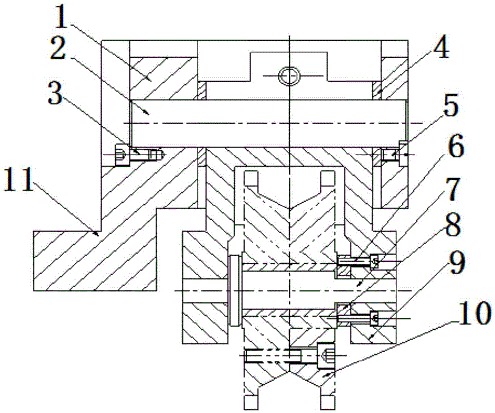
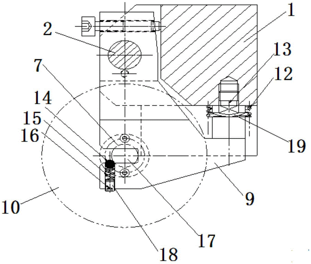
[0022] Such as figure 1 and figure 2 Shown, this lathe chamfering tool rest device, comprises the chamfering frame that is contained on the cutter head of lathe, chamfering frame, comprises the tool rest inner body 9 that chamfering knife 10 is installed on one end and is located at the tool rest inner body 9 other end peripherals and knife rest inner body 9 are connected by the knife rest outer body 1 of rotating shaft 2, and the knife rest inner body 9 can rotate around rotating shaft 2 small angles; A spring 12 is arranged between the outer body 1 of the frame; a top post 13 pressed on the inner body 9 of the tool holder is provided on the outer body 1 of the tool holder when the chamfering knife 10 is chamfered.

[0023] In the lathe chamfering tool rest device, the chamfering frame ...


PUM


Abstract

The invention discloses a chamfering knife rest device for a lathe. The chamfering knife rest device comprises a chamfering frame installed on a cutter plate of the lathe. The chamfering frame comprises an inner knife rest body provided with a chamfering knife at one end, and an outer knife rest body arranged on the periphery of the other end of the inner knife rest body and connected with the inner knife rest body through a rotating shaft, and a spring is arranged between one end, provided with the chamfering knife, of the inner knife rest body and the outer knife rest body. The outer knife rest body is provided with a supporting column attached to the inner knife rest body when the chamfering knife carries out chamfering. According to the chamfering knife rest device for the lathe, chamfering, burr removing and turning of parts such as gears are combined into one process and can be finished on the lathe together, the cost of equipment operation, management, manual work and the like can be effectively lowered, automatic meshing of knife teeth and part teeth can be achieved, the operation difficulty of workers can be lowered, and the work efficiency can be improved.

Description

technical field [0001] The invention relates to a chamfering knife installation device for chamfering and deburring gear parts, in particular to a chamfering tool holder device for a lathe. Background technique [0002] At present, for the chamfering of gear parts, most enterprises use special chamfering machines, whose main structure includes a mounting seat for mounting gear parts and a chamfering machine equipped with a chamfering knife. The chamfering of gear parts by this special machine has the following disadvantages: First, a separate process is used for chamfering, which increases the cost of equipment, management and labor. Secondly, the chamfering machine cannot completely remove the burr on the end face of the part after chamfering; it affects the axial dimension and the roughness of the end face of the part, and requires subsequent finishing. Thirdly, when the chamfering machine is used, it is necessary to manually identify the teeth, which increases the diffic...

Claims


Application Information

Patent Timeline
Patent Type & Authority Patents(China)
IPC IPC(8): B23F19/10B23F23/00
Inventor 付红亮唐升军张小山
Owner WUHU WANLIYANG TRANSMISSION CO LTD
Why Eureka
Try Eureka