
S-shaped wind wheel

A wind wheel and anemometer technology, which is applied to wind turbines, wind turbine combinations, wind turbine control, etc., can solve the problems of reduced fan stiffness, troublesome support rods, low success rate, etc., and can compensate for the deviation of hole positions. , The effect of reducing installation cost and improving utilization efficiency

Active Publication Date: 2014-04-23
KUNSHAN SUNLAITE NEW ENERGY
View PDF4 Cites 1 Cited by
  • Summary
  • Abstract
  • Description
  • Claims
  • Application Information

AI Technical Summary

Problems solved by technology

[0004] This technical solution has the following defects: the support rod is troublesome to manufacture and the cost is relatively high
At this time, it is difficult to ensure the coaxiality between the installation hole and the hole on the blade, and the installation is also troublesome.
②The contact area between the metal wire and the blade is small, so that when the wind is strong, the local force on the blade is relatively large, and it is easy to cause it to be damaged due to large internal stress
And the metal wire is easy to bend when the wind is strong, resulting in a decrease in the stiffness of the entire fan
The existing wind wheel assembly takes a long time to assemble, it is difficult to determine the position of the hole during assembly, it is difficult to assemble, and the success rate is not high, and the labor cost is high

Method used


Image

  • S-shaped wind wheel
  • S-shaped wind wheel
  • S-shaped wind wheel

Examples


Embodiment Construction

[0018] The preferred embodiments of the present invention will be described below in conjunction with the accompanying drawings. It should be understood that the preferred embodiments described here are only used to illustrate and explain the present invention, and are not intended to limit the present invention.

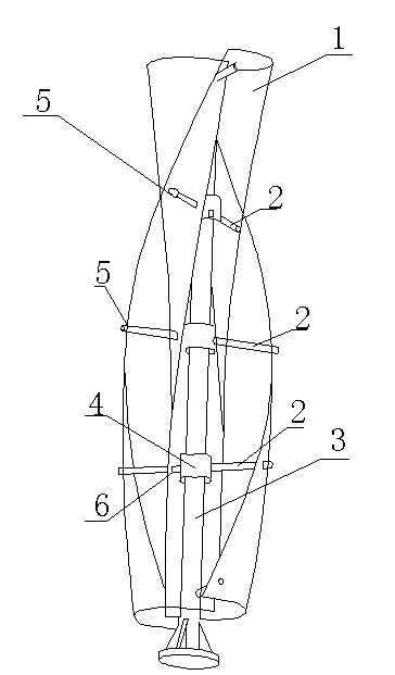
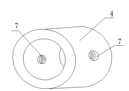
[0019] Such as figure 1 , figure 2 As shown, an S-shaped wind wheel includes fan blades 1, studs 2, a central shaft sleeve 4, a central shaft 3 and a generator, the central shaft 3 is fixed on the generator, and the central shaft sleeve 4 is fixed on the central shaft 3 Above, the central shaft sleeve 4 is provided with an opening 7, the opening 7 is provided with an internal thread, one end of the stud 2 is arranged on the external thread corresponding to the internal thread, and one end of the stud 2 is fixed on the central shaft sleeve 4 through threads. The other end of the stud 2 is fixedly connected with the fan blade 1 .

[0020] Wherein, the top of the ce...


PUM


Abstract

The invention discloses an S-shaped wind wheel. The S-shaped wind wheel comprise a fan blade, studs, a central shaft sleeve, a central shaft and a generator, wherein the central shaft is fixedly arranged on the generator; the central shaft sleeve is fixedly arranged on the central shaft, and is provided with an opening; an inner thread is formed in the opening; one end of each stud is arranged on an outer thread corresponding to the inner thread; one end of each stud is fixedly arranged on the central shaft sleeve in a threaded manner, and the other end of the stud is fixedly connected with the fan blade. The central shaft sleeve is arranged on the central shaft, the fan blade is connected with the central shaft through the studs, the central shaft is provided with a thread hole which is threaded with a screw rod, and the screw rod is fixed through the screw rod and the central shaft. Since the central shaft can rotate by 180 degrees, the deviation of a hole position on the blade is compensated, the installing difficulty in lowered, and the installation success rate is increased, thereby fulfilling the aim of lowering the installing cost.

Description

technical field [0001] The invention relates to the field of wind power generation equipment, in particular to an S-shaped wind rotor. Background technique [0002] At present, with the influence of factors such as the energy crisis and environmental deterioration, people have paid great attention to renewable clean energy such as wind energy and solar energy, and have achieved great results and widely used, especially the combination of solar energy and wind energy. The application of complementary systems overcomes the instability of work caused by adverse factors such as cloudy weather and variable wind speed. At present, the wind-solar hybrid system is widely used in residential roads, industrial parks, tourist scenic spots, parks, courtyard green belts, squares, pedestrian streets, fitness and leisure squares and other places. Vertical axis wind turbines have been available for many years, and they have the characteristics of high utilization rate of wind energy, low s...

Claims


Application Information

Patent Timeline
IPC IPC(8): F03D9/00F03D3/06F03D7/06
CPCY02E10/74
Inventor 朱猛詹文贤宋贤杰顾军吴聪萍邹志刚
Owner KUNSHAN SUNLAITE NEW ENERGY
Learn More