Variable turbocharger

A turbocharger, variable technology, applied in the direction of mechanical equipment, combustion engines, machines/engines, etc., can solve problems such as difficulty, loose and small adjustment of connecting rod joints, complex structure, etc., and achieve the effect of simple structure

Inactive Publication Date: 2003-10-01
KOMATSU LTD
View PDF1 Cites 4 Cited by
  • Summary
  • Abstract
  • Description
  • Claims
  • Application Information

AI Technical Summary

Problems solved by technology

[0005] However, in the above configuration, it is necessary to convert the linear motion of the rod 81 into a rotational motion through the connecting arm 76, and its structure is complicated.
In addition, there are many connecting parts of the connecting rod, so looseness often occurs and fine adjustment is difficult.

Method used


Image

  • Variable turbocharger
  • Variable turbocharger
  • Variable turbocharger

Examples


Embodiment Construction

[0029] Hereinafter, embodiments of the variable turbocharger according to the present invention will be described in detail with reference to the drawings.

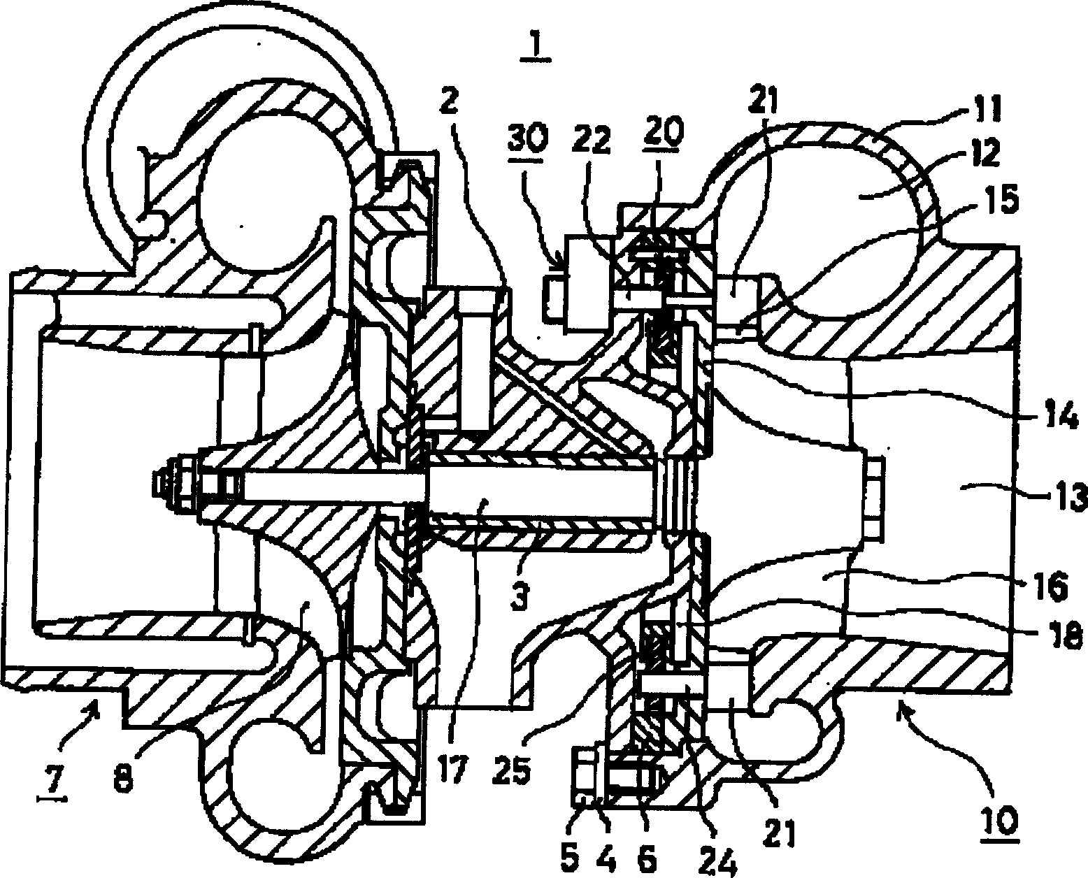
[0030] figure 1 It is a side sectional view of the variable turbocharger 1 . exist figure 1 Among them, a variable turbocharger 1 is composed of an air supply compressor and an exhaust turbine 10 .

[0031] The exhaust turbine 10 is provided in the middle of an exhaust flow path of an engine not shown in the figure, and has an exhaust-side casing 11 that guides the inflow and outflow of exhaust gas, and an exhaust-side casing 11 that houses an exhaust-side casing 11. .

[0032] The exhaust-side casing 11 has an exhaust gas inflow portion 12 integrally formed on the outer peripheral side and a substantially cylindrical exhaust gas outflow portion 13 formed in the central portion. Inside the exhaust side housing 11, an exhaust side inner plate 14 is provided to block the opening on the side opposite to the exhaust gas...


PUM


Abstract

A variable turbocharger, in which a blade (31) is embedded on a rotating drive shaft (22) of a nozzle blade not shown in the figure fixed on the front end, and the rotation is stopped by a key (32). The vane (31) is rotatably housed in a fan-shaped casing (33) around the rotating drive shaft (22), and the casing (33) is separated into a pressure chamber (34) and a discharge chamber (35). An introduction port (36) for introducing pressure oil is provided in the pressure chamber (34), and a discharge port (37) is provided in the discharge chamber (35). A spring (40) is interposed between the vane (31) in the discharge chamber (35) and the wall surface (35a) of the housing (33) to press the vane (31) toward the pressure chamber (34) side. When the displacement is small, the pressure oil is supplied to the pressure chamber (34), the vane (31) is rotated to the side of the discharge chamber (35) and the nozzle vane is closed. Its structure is simple and it is easy to make small adjustments to the opening of the nozzle blades.

Description

technical field [0001] The present invention relates to a turbocharger, and more particularly to a variable turbocharger having nozzle vanes that adjust the flow rate of exhaust gas flowing into an exhaust turbine. Background technique [0002] Conventionally, as a method of compressing air and sucking a large amount of air into an air cylinder, there is known a turbocharger that utilizes exhaust energy of an engine to operate an exhaust turbine to drive a centrifugal compressor. In this kind of turbocharger, since the exhaust gas of the engine is used, the exhaust gas flow rate is low in the low-speed rotation area of ​​the engine, and the exhaust turbine also forms a low-speed rotation, so that sometimes the air in the centrifugal compressor cannot be fully exhausted. compression. Therefore, in order to improve this characteristic, a variable turbocharger is used. An on-off valve is set on the exhaust flow path around the exhaust turbine rotor of the turbocharger. When th...

Claims


Application Information

Patent Timeline
Patent Type & Authority Applications(China)
IPC IPC(8): F02B37/24
CPCY02T10/12F02B37/24
Inventor 西山利彦杉户博饭野任久
Owner KOMATSU LTD
Why Eureka
Try Eureka