
An improved structure of the oil injection nozzle of an oil injection machine

A technology of oil injection nozzle and oil injection machine, which is applied in the direction of engine lubrication, mechanical equipment, engine components, etc. It can solve the problems of oil dripping easily, achieve the effects of preventing falling, increasing the length of the edge line, and increasing the pulling force

Active Publication Date: 2016-08-24
SICHUAN NINGJIANG SHANCHUAN MACHINERY
View PDF5 Cites 0 Cited by
  • Summary
  • Abstract
  • Description
  • Claims
  • Application Information

AI Technical Summary

Problems solved by technology

[0004] The purpose of the present invention is to provide an improved structure of the oil injection nozzle of the oil injection machine to solve the problem in the prior art that the oil injection nozzle of the oil injection machine is easy to drip oil after closing, so as to achieve the purpose of no oil drip and reduce the process of workers wiping the shock absorbing oil

Method used


Image

  • An improved structure of the oil injection nozzle of an oil injection machine

Examples


Embodiment

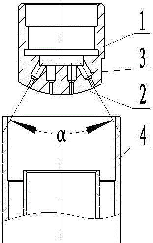
[0020] Such as figure 1 As shown, the improved structure of the oil injection nozzle of the oil injection machine in the present invention includes an oil injection nozzle body 1, the oil injection nozzle body 1 is cylindrical, and has a cylindrical cavity inside, and the cavity is used as an injection channel for shock absorbing oil. Both ends of the oil nozzle body are open, one end is used to communicate with the oil injection machine, and the other end is inserted into the interior of the shock absorber 4 as an oil outlet. The oil outlet of the oil injection nozzle body 1 forms a closed end 2, The outside of the closed end 2 is arc-shaped, and then a plurality of through holes 3 are arranged on the closed end 2, the axes of the through holes 3 are perpendicular to the arc surface of the closed end 2, and the through holes 3 have two inner cylindrical cavities with different diameters. The two cylindrical cavities are connected by a tapered surface to form a stepped structu...


PUM


Abstract

The invention discloses an improvement structure of an oil nipple of an oiling machine. The improvement structure comprises an oil nipple body which is cylindrical, one of two ports of the oil nipple body is used for being connected with the oiling machine, the other of the two ports is used as an oil outlet, the oil outlet of the oil nipple body is closed to form a closed end, and a plurality of through holes are formed in the closed end. According to the improvement structure of the oil nipple of the oiling machine, closed space is used to form a vacuum so as to prevent 98% of damping oil from leaking; subsequently, the through holes are used as oil outlet channels, so that the area of a single oil outlet channel is reduced, the edge line of an outlet is prolonged, and per unit length of the edge line is increased; the tensile force borne by oil is fixed, by means of the viscosity of the damping oil, volume of oil drops is reduced while the edge line is prolonged, meanwhile, the viscosity tensile force borne by oil is increased, and the tensile force borne by small-volume oil drops is larger than gravity borne by the oil drops, so that the problem of dropping oil is solved, and the purposes of absence of oil dropping and removal of the procedure that workers wipe the damping oil are achieved.

Description

technical field [0001] The invention relates to an oil injection nozzle of an oil injection machine, in particular to an improved structure of an oil injection nozzle of an oil injection machine. Background technique [0002] The structure of the shock absorber is that the piston rod with the piston is inserted into the cylinder, and the cylinder is filled with oil. There is an orifice on the piston, so that the oil in the two spaces separated by the piston can complement each other. Damping is produced when viscous oil passes through the orifice, the smaller the orifice, the greater the damping force, and the greater the viscosity of the oil, the greater the damping force. If the size of the orifice remains the same, when the shock absorber works fast, excessive damping will affect the absorption of shock. Therefore, a disc-shaped leaf spring valve is set at the outlet of the orifice. When the pressure increases, the valve is pushed open, the opening of the orifice become...

Claims


Application Information

Patent Timeline
Patent Type & Authority Patents(China)
IPC IPC(8): F16N21/02
Inventor 段少云
Owner SICHUAN NINGJIANG SHANCHUAN MACHINERY
Learn More