Nondestructive detection device for light path of fiber-optic gyroscope

A fiber optic gyroscope and non-destructive testing technology, which is used in measuring devices, instruments, etc., can solve the problems of inability to observe the back of the fiber and the blocked area, and achieve the effect of avoiding subsequent quality problems, convenient testing, and flexible adjustment.

Active Publication Date: 2014-04-23
BEIJING AEROSPACE TIMES OPTICAL ELECTRONICS TECH
View PDF6 Cites 12 Cited by
  • Summary
  • Abstract
  • Description
  • Claims
  • Application Information

AI Technical Summary

Problems solved by technology

However, after the optical fiber is wound and glued, the optical path at the back end has been closed by the fusion point, and it can no longer be connected to the detection equipment for detection. We can only try to detect the defect of the optical fiber through external observation, and the optical fiber is wound in the fiber ring cavity. This kind of optoelectronic device is relatively close to each other, and the optical fibers are wound into bundles and overlap each other, and the defects on the back of the optical fiber and the shielded area cannot be observed directly with an ordinary microscope

Method used


Image

  • Nondestructive detection device for light path of fiber-optic gyroscope
  • Nondestructive detection device for light path of fiber-optic gyroscope
  • Nondestructive detection device for light path of fiber-optic gyroscope

Examples


Embodiment

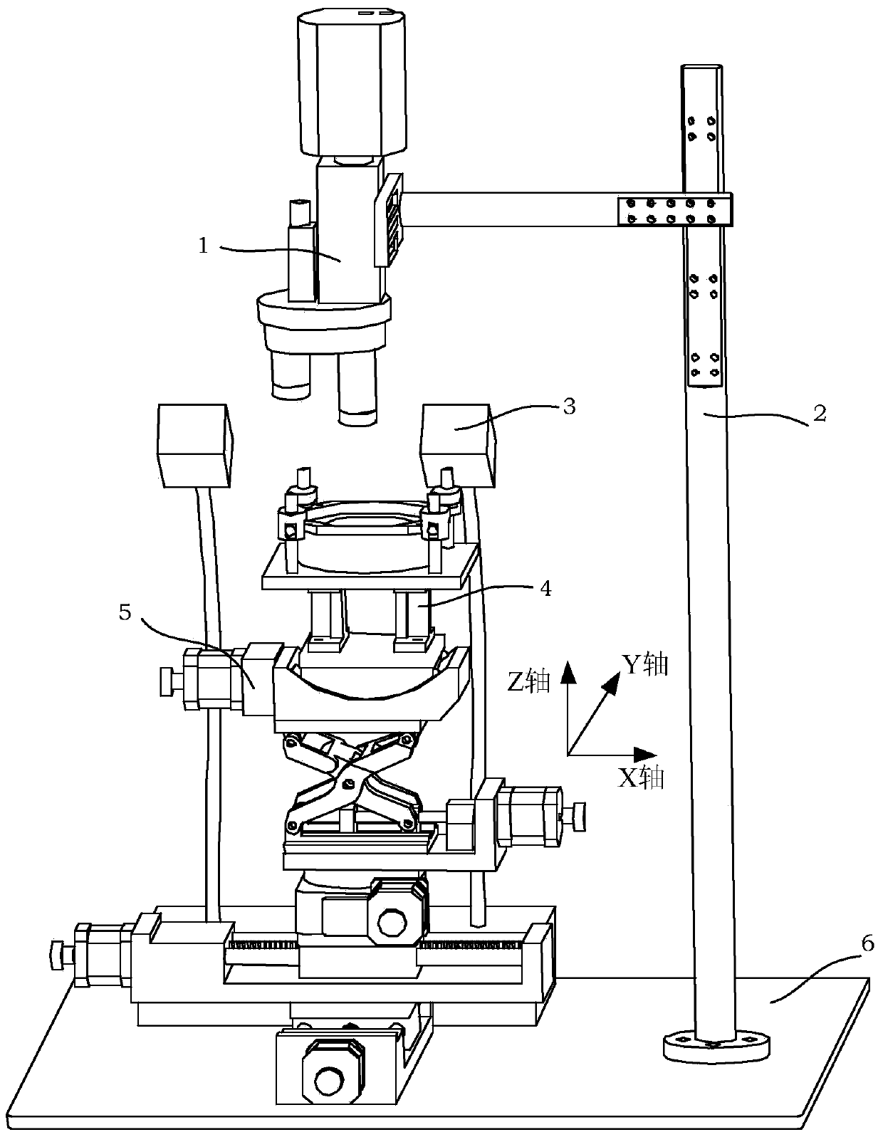
[0046] A fiber optic gyroscope optical path non-destructive testing device, such as figure 1 As shown, the device includes an infrared imaging system 1, a lens holder 2, an illumination system 3, a fiber optic gyro fixing assembly 4, a five-degree-of-freedom displacement device 5, and an optical plate 6;

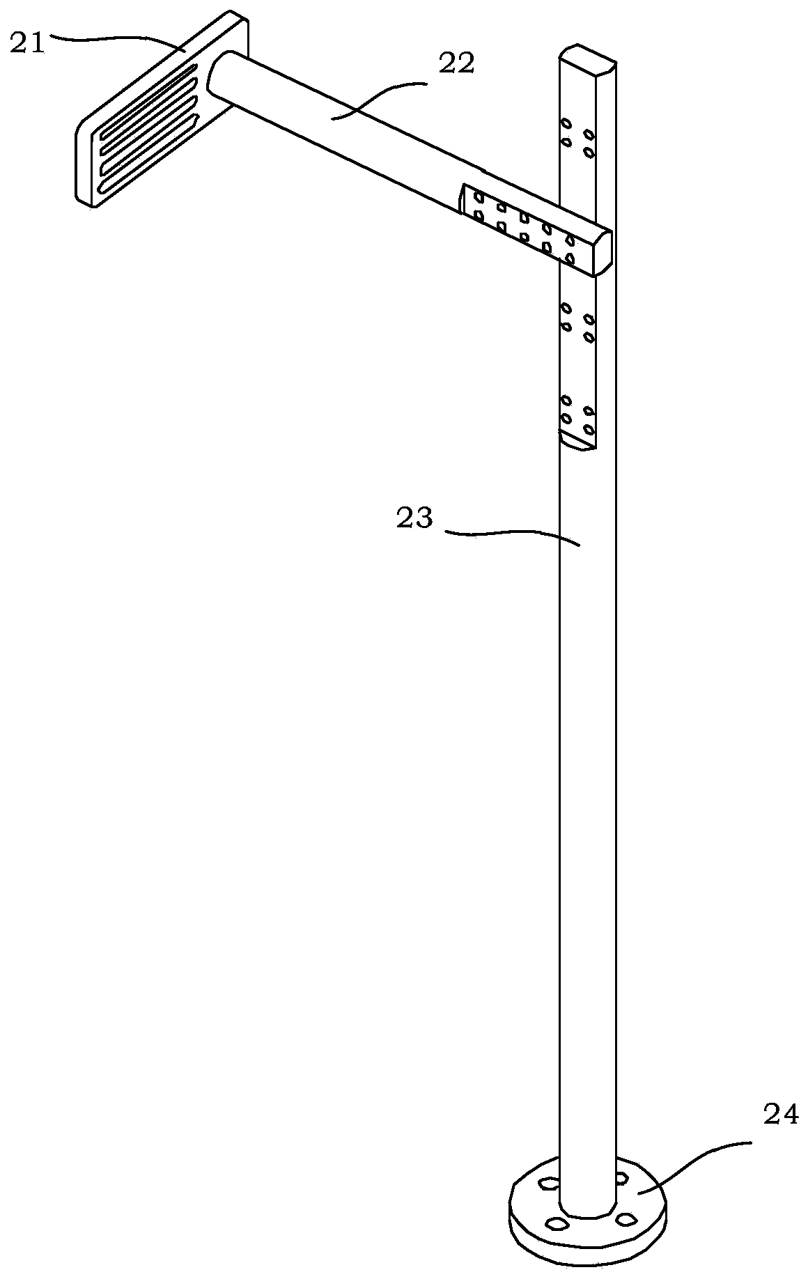
[0047] The infrared imaging system 1 is fixedly connected with the lens bracket 2, the lens bracket 2 is installed on the optical flat panel 6, the infrared imaging system 1 is perpendicular to the optical flat panel 6, the lighting system 3 is installed on the optical flat panel 6, and the lighting system 3 is fixed to the optical fiber gyroscope. The optical fiber gyroscope to be tested on the component 4 is facing, the optical fiber gyroscope fixing component 4 is installed on the five-degree-of-freedom displacement device 5, and the five-degree-of-freedom displacement device 5 is installed on the optical plate 6;

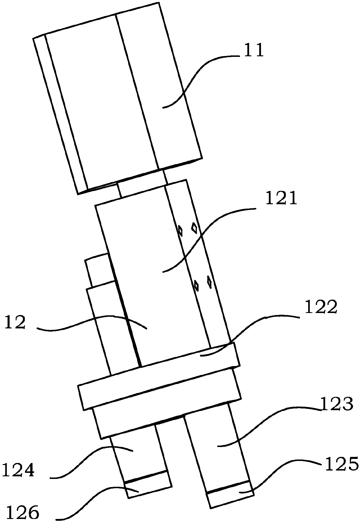
[0048] like figure 2 As shown, the infrared imaging sy...


PUM


Abstract

The invention relates to a nondestructive detection device for a light path of a fiber-optic gyroscope, and belongs to the technical field of fiber-optic gyroscope detection. The device comprises an infrared imaging system, a lens bracket, an illumination system, a fiber-optic gyroscope fixing component, a five-degree-of-freedom displacement device and an optical flat plate, wherein the infrared imaging system is fixedly connected with the lens bracket; the lens bracket is arranged on the optical flat plate; the infrared imaging system is perpendicular to the optical flat plate; the illumination system is arranged on the optical flat plate, and is just opposite to a fiber-optic gyroscope to be detected, which is fixed on the fiber-optic gyroscope fixing component; the fiber-optic gyroscope fixing component is arranged on the five-degree-of-freedom displacement device which is arranged on the optical flat plate.

Description

technical field [0001] The invention relates to a non-destructive detection device for the optical path of an optical fiber gyroscope, in particular to a device for detecting defects in the optical path at the rear end of an optical fiber gyroscope, which belongs to the technical field of optical fiber gyroscope detection. Background technique [0002] Fiber optic gyro is a new type of all-solid-state inertial instrument with high reliability and long life. After more than ten years of hard work, domestic fiber optic gyro technology has been successfully applied to many weapons and aerospace models. With the in-depth advancement of various types of tasks, the reliability and long life requirements of fiber optic gyroscopes are getting higher and higher. [0003] The fiber optic gyroscope's light source, fiber coupler, Y waveguide, fiber ring and other optical devices are connected to each other through optical fibers, and optical fibers are the weak link in reliability. In ...

Claims


Application Information

Patent Timeline
Patent Type & Authority Applications(China)
IPC IPC(8): G01C25/00
CPCG01C25/00
Inventor 葛文谦王巍高峰单联洁马玉洲刘朝阳
Owner BEIJING AEROSPACE TIMES OPTICAL ELECTRONICS TECH
Why Eureka
Try Eureka