Steel plate surface defect detection system and method based on machine vision

A defect detection and machine vision technology, applied in the field of defect detection, can solve problems such as difficulty in achieving precision and quantification, difficulty in memory storage and analysis, and many infrared detections, achieve high-speed and accurate image acquisition of steel plate surface, improve image acquisition efficiency, Overcome the slow response effect

Inactive Publication Date: 2020-03-10
NANJING UNIV OF SCI & TECH
View PDF5 Cites 4 Cited by
  • Summary
  • Abstract
  • Description
  • Claims
  • Application Information

AI Technical Summary

Problems solved by technology

Manual inspection is a simple, repetitive, fast and highly concentrated work, which not only puts a lot of pressure on the inspectors, but also must reduce the moving speed of the steel plate during the visual inspection process, and the corresponding As the steel plate rolling speed decreases, the production efficiency will inevitably decrease. At the same time, the inspectors will inevitably be objectively affected by fatigue, mood, feeling and technical level, so it is difficult to be accurate and quantitative. In addition, the memory storage and analysis of defects is also very difficult. Difficult; eddy current testing uses the principle of electromagnetic induction. Although non-contact measurement can be achieved and the speed is fast, its penetration depth is limited and it needs to be close to the surface to be tested. When the surface to be tested is rough, it will affect the detection. As a result, the detection accuracy is reduced; there are many restrictions on the use of infrared detection, and detection is generally only carried out in a small offline range; it can be seen that the detection accuracy of the above methods is not high

Method used


Image

  • Steel plate surface defect detection system and method based on machine vision
  • Steel plate surface defect detection system and method based on machine vision

Examples


Embodiment Construction

[0025] In order to make the purpose, technical solution and advantages of the present application clearer, the present application will be further described in detail below in conjunction with the accompanying drawings and embodiments. It should be understood that the specific embodiments described here are only used to explain the present application, and are not intended to limit the present application.

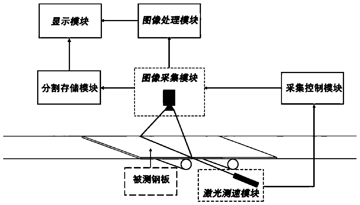
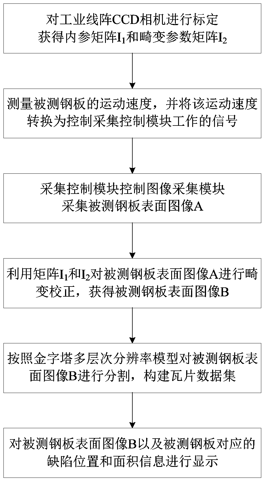
[0026] combine figure 1 , the present invention provides a steel plate surface defect detection system based on machine vision, comprising: a transmission module, a laser speed measurement module, an acquisition control module, an image acquisition module, an image processing module, a display module and a segmentation storage module;

[0027] The transmission module is used to drive the steel plate under test to move along the horizontal plane;

[0028] The laser speed measurement module is used to measure the moving speed of the tested steel plate, and convert the movin...


PUM


Abstract

The invention discloses a steel plate surface defect detection system and method based on machine vision. The system comprises a transmission module, a laser speed measurement module, an acquisition control module, an image acquisition module, an image processing module, an image segmentation and storage module and an image display module, wherein the transmission module is used for driving a detected steel plate to move; the laser speed measurement module is used for generating a signal for controlling the acquisition control module to work; the acquisition control module is used for controlling the image acquisition module to work; the image acquisition module is used for acquiring a surface image of the measured steel plate; the image processing module is used for carrying out preprocessing and defect detection on the surface image of the detected steel plate; the image segmentation and storage module is used for segmenting the surface image of the measured steel plate; and the image display module is used for displaying the image of the detected steel plate and the defect information corresponding to the detected steel plate. The method implements defect detection based on thesystem. According to the invention, non-contact steel plate defect detection can be achieved, and the high-resolution steel plate surface image and defect information are displayed. The system and method disclosed by the invention have the advantages of high acquisition speed, high resolution, fast and smooth display, high detection accuracy and the like, and have broad application prospects.

Description

technical field [0001] The invention belongs to the field of defect detection, and in particular relates to a machine vision-based steel plate surface defect detection system and method. Background technique [0002] Machine vision technology refers to the use of computers to realize human visual functions, that is, to use computers to realize the recognition of the objective three-dimensional world, mainly including research on image acquisition, processing, analysis, output and display. As an important branch of computer science, machine vision technology has developed rapidly in the past 30 years, and its application fields are all over industry, agriculture and military. Through the intersection and penetration of computer technology to non-destructive testing technology, machine vision has become a vital branch of non-destructive testing technology, and has opened up a new application field of non-destructive testing technology. At present, the industrial visual inspec...

Claims


Application Information

Patent Timeline
Patent Type & Authority Applications(China)
IPC IPC(8): G01N21/89G01N21/93
CPCG01N21/8901G01N21/93G01N2021/8909G01N2021/8861G01N2021/8874
Inventor 陈文建陈瑞李武森王小卓裘俊哲
Owner NANJING UNIV OF SCI & TECH
Why Eureka
Try Eureka