
A system and method for displaying application information of pre-plan linkage

A technology for applying information and display systems, applied in the fields of information integration and computer applications, which can solve the problems of high cost, heavy workload, and impact on display effects, and achieve the effects of reducing construction costs, reducing work requirements, and improving construction efficiency

Active Publication Date: 2017-08-04
BEIJING E TECHSTAR
View PDF3 Cites 0 Cited by
  • Summary
  • Abstract
  • Description
  • Claims
  • Application Information

AI Technical Summary

Problems solved by technology

[0005] Its defects are: due to the different display methods and forms of each application system, and the theme colors are also inconsistent, resulting in poor consistency and harmony of the results formed by the combination, which greatly affects the final display effect
[0008] Its disadvantages are: due to the need to access data, when the number of related application systems in the emergency command center (the center where other large screens are located) is large (the number of related actual production systems in the general emergency command center is relatively large), it is necessary to develop There are many data interfaces, and the data display needs to be re-displayed according to the display requirements, resulting in a huge workload
In addition, since these emergency systems are often built by other manufacturers before the emergency command center is built, if the data interface is to be developed, these manufacturers are often required to intervene, which involves development costs, development cycles and many other technical issues, resulting in the entire very expensive to implement

Method used


Image

  • A system and method for displaying application information of pre-plan linkage
  • A system and method for displaying application information of pre-plan linkage
  • A system and method for displaying application information of pre-plan linkage

Examples


Embodiment Construction

[0045] In order to make the object, technical solution and advantages of the present invention clearer, the present invention will be further described in detail below in conjunction with the accompanying drawings. It should be understood that the specific embodiments described here are only used to explain the present invention, and are not intended to limit the present invention.

[0046] Pre-plan linkage: The emergency plan drives the corresponding application system to form a visual information display screen or complete certain specific logical actions;

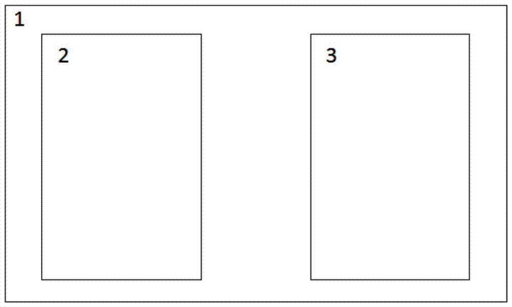
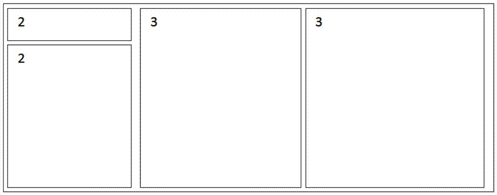
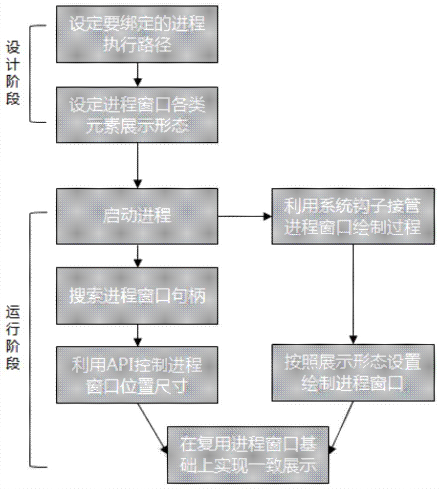
[0047] Such as Figure 1-6 As shown, the present invention discloses a scheme linkage application information display system and method:

[0048] The basic idea of ​​the present invention is to develop an information display system. For new data (that is, data without a ready-made display form, that is, data provided by a windowless process), the system provides commonly used form components such as text and charts for ...


PUM


Abstract

The present invention discloses a system and method for displaying application information linked by plans: for new data (that is, data without a ready-made display form, that is, data provided by a windowless process), the system provides commonly used components such as text and charts for display . For old data (that is, data that has provided mature display forms in existing business systems, including emergency professional systems inside the emergency command center and other professional production systems outside the center, that is, data provided by window processes), the system provides a The common process component realizes the position linkage between processes, and can realize the adjustment of the color and even the display form of the process window. Adopting the present invention can effectively avoid the secondary development of these existing systems. On the one hand, it can reduce the workload of the development contractor in the system implementation process, and on the other hand, it also reduces the work requirements for the existing system construction manufacturers, so as a whole. The construction cost of the system is reduced, and the construction efficiency is improved.

Description

technical field [0001] The present invention relates to the fields of computer application and information integration, and in particular to a system and method for displaying application information linked with plans. Background technique [0002] With the construction and promotion of the emergency system, the emergency plan drives the relevant application information system in the emergency command center to form an information splicing screen in line with the current emergency application scenario, or complete the corresponding application logic (such as SMS group notification, etc.), to form the following The linkage application centered on the emergency plan has become an urgent practical application demand. [0003] One of the existing technical solutions: [0004] At present, the integrated display of large-screen information in the emergency command center (the center where other large-screens are located) generally adopts the method of splicing graphics windows of...

Claims


Application Information

Patent Timeline
Patent Type & Authority Patents(China)
IPC IPC(8): G06F9/44
Inventor 钱苏晋
Owner BEIJING E TECHSTAR
Learn More