Test method and test system for interlocking software
A test system and test method technology, applied in the direction of software testing/debugging, etc., can solve problems such as boring, tasteless, and insufficient testing in the testing process, and achieve the effects of improving accuracy, reducing burden, and increasing the degree of automation
- Summary
- Abstract
- Description
- Claims
- Application Information
AI Technical Summary
Problems solved by technology
Method used
Image

Examples
Embodiment Construction
[0062] The specific implementation manners of the present invention will be further described below in conjunction with the drawings and examples. The following examples are only used to illustrate the technical solution of the present invention more clearly, but not to limit the protection scope of the present invention.
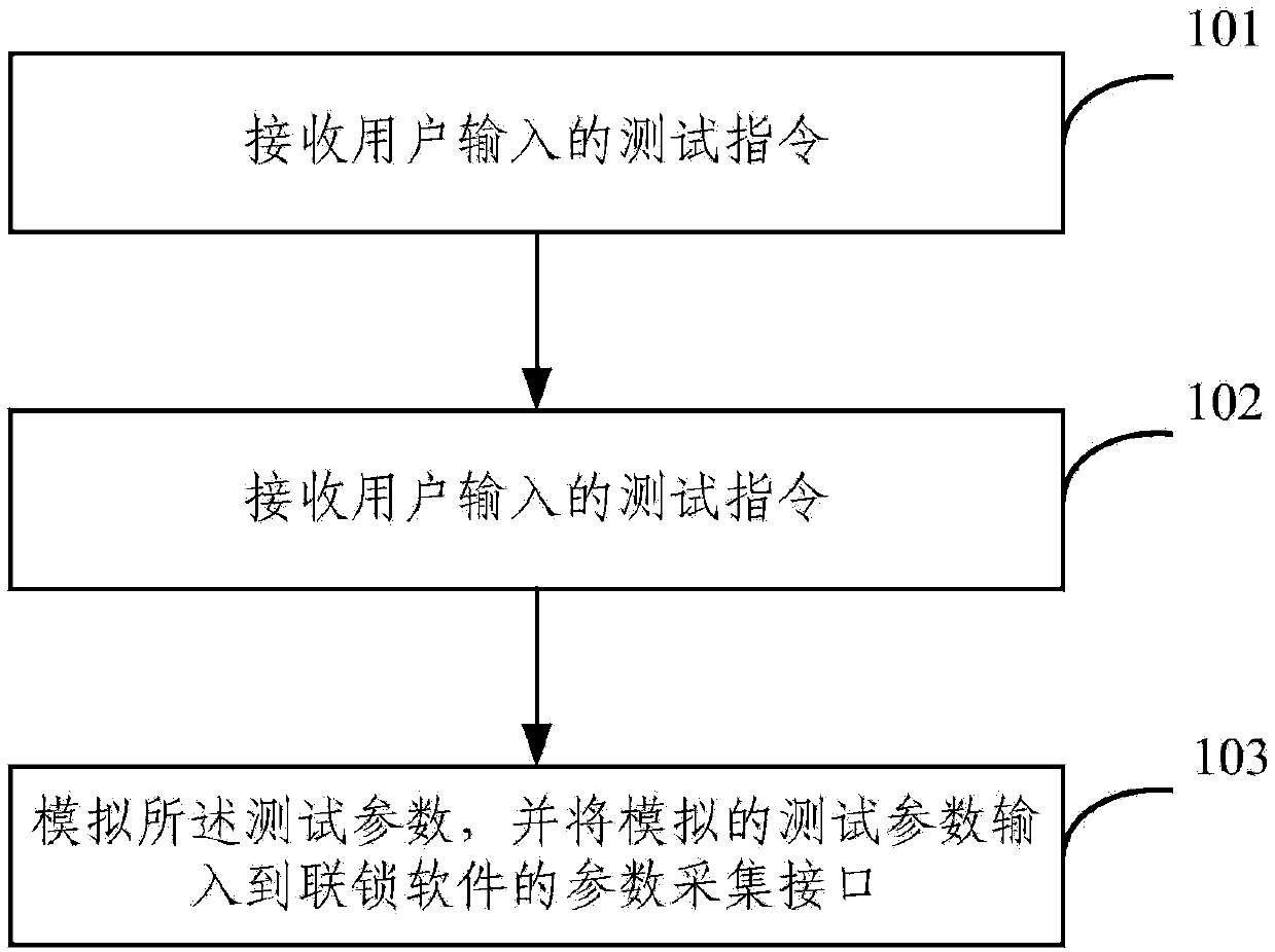
[0063] The invention provides a method for testing interlocking software, which is used for testing the interlocking software of the interlocking system, such as figure 1 As shown, the method includes:
[0064] In step 101, a test instruction input by a user is received, and the test instruction is used to indicate the test content of the current test.
[0065] Step 102, determining the test parameters needed to complete the test content.
[0066] Step 103, simulating the test parameters, and inputting the simulated test parameters into the parameter acquisition interface of the interlocking software.
[0067] In the test method provided by Embodiment 1 ...
PUM
 Abstract
Description
Claims
Application Information
PatSnap Eureka turns technology decisions into work you can execute. Powered by our Innovation Knowledge Graph, it runs expert workflows across engineering, life sciences, materials and intellectual property. Get your review-ready output in minutes.


