Sealing structure between motor shaft and motor cover

A technology of motor shaft and sealing structure, applied in electrical components, electromechanical devices, electric components, etc., can solve the problems of unsatisfactory waterproof performance of the motor, affecting the service life of the motor, and the motor being prone to water and moisture, so as to ensure normal and safe operation, The effect of improving the service life and improving the waterproof performance

Active Publication Date: 2014-04-23
绍兴摩泰机电科技有限公司
View PDF6 Cites 10 Cited by
  • Summary
  • Abstract
  • Description
  • Claims
  • Application Information

AI Technical Summary

Problems solved by technology

[0002] For motors working outdoors or in humid environments, due to long-term rain, the inside of the motor is very easy to get water and moisture, causing the motor to short-circuit and burn out
Since the motor shaft protrudes from the motor cover, the sealing between the motor shaft and the motor cover is very important. If the seal is not good and the motor is damp or water enters, it will directly affect the wire ends and winding wires, causing the motor to be short-circuited and burned In addition, when the motor is placed sideways, water will also flow down the motor cover and seep into the shaft hole of the motor cover. There is no sealing structure between the existing motor cover and the motor shaft, so the waterproof performance of the motor is not ideal, seriously Affect the service life of the motor

Method used


Image

  • Sealing structure between motor shaft and motor cover
  • Sealing structure between motor shaft and motor cover
  • Sealing structure between motor shaft and motor cover

Examples


Embodiment Construction

[0016] The present invention will be further described in detail below with reference to the embodiments of the accompanying drawings.

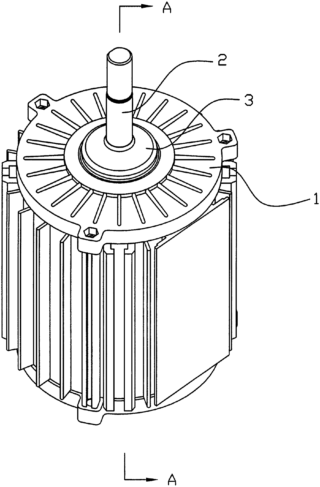
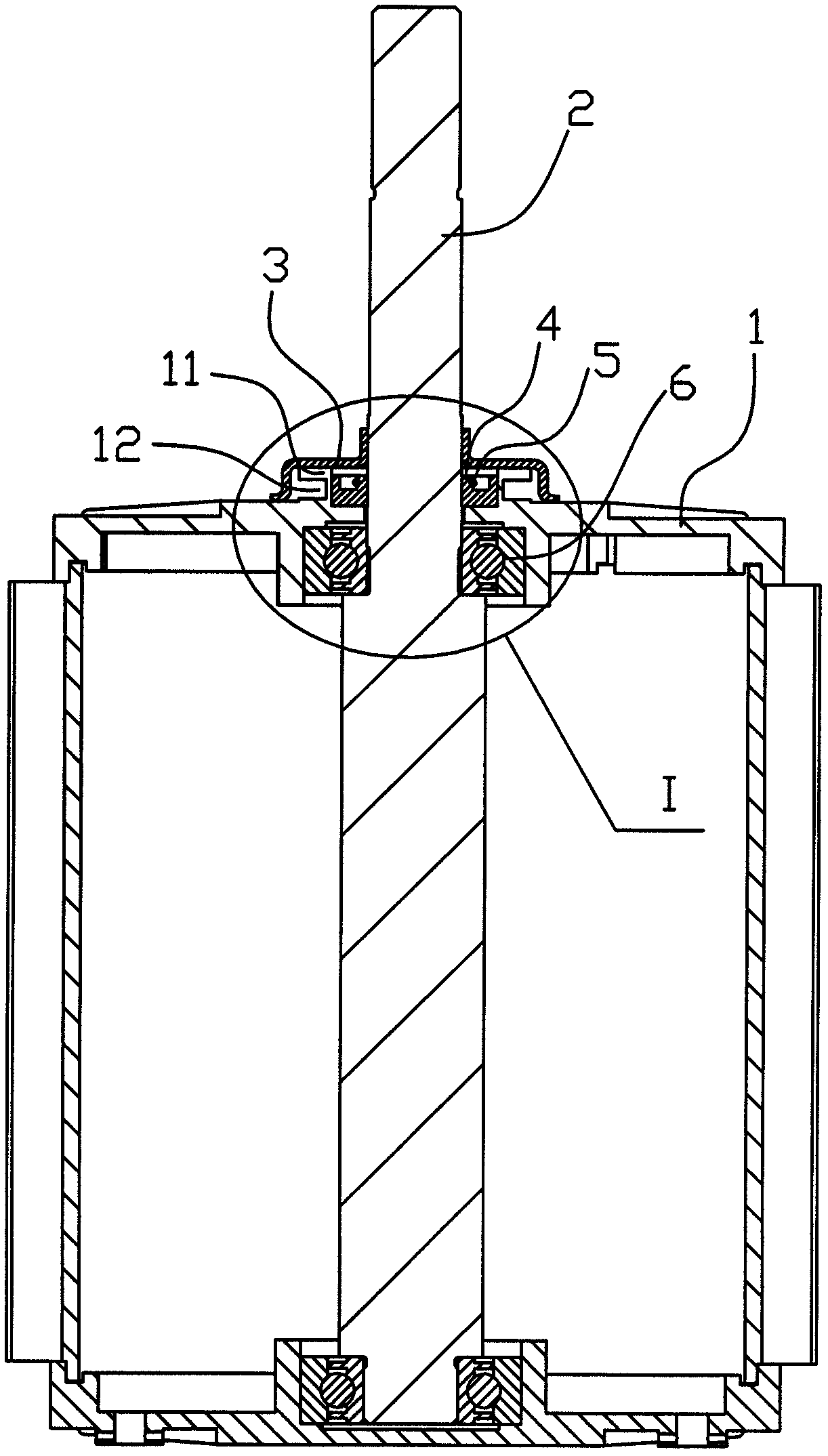
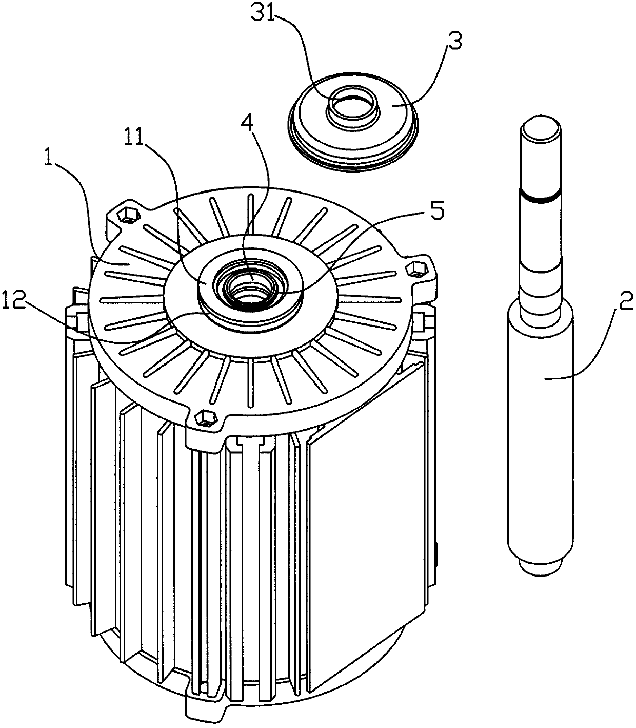
[0017] like Figure 1 to Figure 6 As shown, the sealing structure between the motor shaft and the motor cover in this embodiment includes a motor shaft 2 and a motor cover 1, and the motor cover 1 is provided with a shaft hole extending from one end of the motor shaft 2 coaxial with the bearing 6 13. An annular bump 11 coaxial with the shaft hole 13 is integrally formed on the upper surface of the motor cover 1, and a concave annular shape is formed between the bottom surface of the annular bump 11 and the upper surface of the motor cover 1 to facilitate the outflow of liquid. groove 12, and a cover 3 for water blocking is covered on the annular bump 11, and an annular groove is formed in the middle of the annular bump 11 corresponding to the position of the shaft hole 13, and the annular groove is embedded with A sealing ring 4 that can kee...


PUM


Abstract

The invention discloses a sealing structure between a motor shaft and a motor cover. The sealing structure comprises the motor shaft (2) and the motor cover (1); the motor cover (1) is provided with a shaft hole (13) which is coaxial with a bearing (6) and used for one end of the motor shaft (2) to extend out. The sealing structure is characterized in that the upper surface of the motor cover (1) is a circular lug (11) coaxial with the shaft hole (13) through integral forming; a concave circular groove (12) facilitating the outflow of liquid is formed between the bottom of the annular lug (11) and the upper surface of the motor cover (1); a housing (3) used for blocking water covers the circular lug (11). The sealing structure has the advantages that when a motor is arranged laterally, water on the motor can flow out of the circular groove along the motor cover and cannot enter the shaft hole of the motor cover; when the motor is straightly arranged, the housing has a waterproof function; besides, a sealing ring is formed outside the shaft hole, and an elastic retainer ring is sleeved outside the sealing ring, so that the sealing ring can be closely fitted with the motor shaft, the sealing property between the motor shaft and the motor cover is further improved and the water is prevented from entering the motor.

Description

technical field [0001] The invention belongs to the technical field of motor production, in particular to a sealing structure between a motor rotating shaft and a motor cover. Background technique [0002] For motors that work outdoors or in humid environments, due to prolonged rain, the inside of the motor is very easy to get water and damp, causing the motor to be short-circuited and burned. Since the motor shaft protrudes from the motor cover, the sealing between the motor shaft and the motor cover is very important. If the sealing is not good and the motor is damp or water enters, it will directly affect the wire head and winding wire, causing the motor to be short-circuited and burned. , In addition, when the motor is placed sideways, the water will also flow down the motor cover and penetrate into the shaft hole of the motor cover. There is no sealing structure between the existing motor cover and the motor shaft, so the waterproof performance of the motor is not ideal...

Claims


Application Information

Patent Timeline
Patent Type & Authority Applications(China)
IPC IPC(8): H02K5/124
Inventor 徐济高贾元振裘霖富徐祖平杨友生
Owner 绍兴摩泰机电科技有限公司
Why Eureka
Try Eureka