Supercharge Your Innovation With Domain-Expert AI Agents!

Motor end cover and bearing assembling structure

A technology of bearing assembly and motor end cover, which is applied in the direction of electromechanical devices, manufacturing motor generators, electrical components, etc., can solve the problems of the total length of the motor, cannot satisfy customers, and occupy the external space of the motor base, so as to shorten the total length and reduce the cost effect

Active Publication Date: 2014-04-23
无锡欧瑞京机电有限公司
View PDF9 Cites 1 Cited by
  • Summary
  • Abstract
  • Description
  • Claims
  • Application Information

AI Technical Summary

Problems solved by technology

When it is found that the total length of the motor is much smaller than the total length of our standard motor, many manufacturers are helpless, such as figure 1 structure shown, figure 1 It is a schematic diagram of a traditional motor end cover and bearing assembly structure. The traditional motor end cover and bearing assembly structure includes a motor shaft 10, a bearing 11 is mounted on the motor shaft 10, and a bearing outer cover 12 is installed outside the bearing 11. The bearing outer cover 12 is connected with an oil pipe 13 through an oil passage, and the bearing 11 and the bearing outer cover 12 of this assembly structure are set through the motor end cover 14, that is, a part of the bearing 11 and the bearing outer cover 12 is located on the motor machine. The rest is located outside the motor frame, and the assembly of the integral bearing exceeds the motor end cover 14, occupying the external space of the motor frame, resulting in a long overall length of the motor, which cannot meet the customer's requirements

Method used


Image

  • Motor end cover and bearing assembling structure
  • Motor end cover and bearing assembling structure

Examples


Embodiment Construction

[0012] The technical solutions of the present invention will be further described below in conjunction with the accompanying drawings and through specific implementation methods.

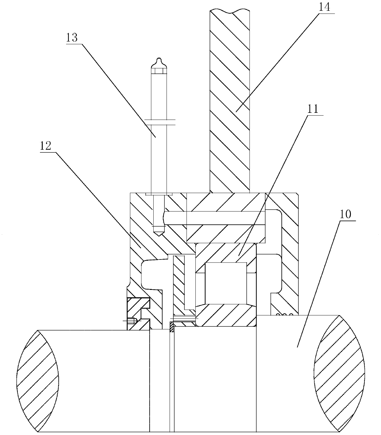
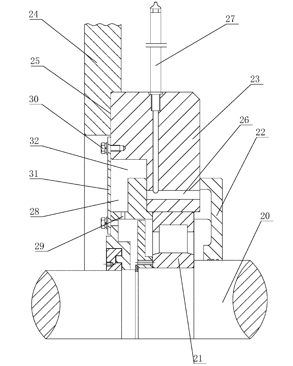
[0013] see figure 2 as shown, figure 2 It is a structural schematic diagram of the assembly structure of the motor end cover and the bearing provided in Embodiment 1 of the present invention.

[0014] In this embodiment, a motor end cover and bearing assembly structure includes a motor shaft 20, a bearing 21, a bearing cover 22, a shaft sleeve 23 and an end cover ring plate 24, and the bearing 21 and the bearing cover 22 are assembled on the On the motor rotating shaft 20 inside the end cover ring plate 24, the inner side of the end cover ring plate 24 is provided with a concave annular groove 25, and the bearing outer cover 22 is provided with a hole for installing a shaft sleeve 23, and the shaft sleeve 23 is an inverted "L"-shaped structure, one end of the shaft sleeve 23 is installed in the ...


PUM


Abstract

The invention discloses a motor end cover and bearing assembling structure, which comprises a motor rotating shaft, a bearing, a bearing outer cover and an end cover ring plate, wherein the bearing and the bearing outer cover are assembled on the motor rotating shaft on the inner side of the end cover ring plate, an inwards concave ring groove is formed in the inner side of the end cover ring plate, a hole for installing a shaft sleeve is formed in the bearing outer cover, one end of the shaft sleeve is installed in the ring groove, the other end of the shaft sleeve is assembled in the bearing outer cover through the hole, an oil path which is communicated with the internal part of the bearing outer cover is formed in the bearing sleeve, an oil pipe is connected onto the oil path, a ring notch is formed in the top of the outer side of the bearing outer cover and a plurality of oil outlets are formed in the bottom part of the ring notch. The motor end cover and bearing assembling structure has the advantages that since the bearing and the bearing outer cover are assembled in the end cover ring plate, the internal space of a motor base is fully utilized, the total length of a motor is shortened, the cost is reduced and the special demands of customers are met.

Description

technical field [0001] The invention relates to a motor, in particular to an assembly structure of a motor end cover and a bearing. Background technique [0002] At present, when customers customize the motor, they will have a requirement for the total length of the motor to adapt to the installation environment of the motor. When it is found that the total length of the motor is much smaller than the total length of our standard motor, many manufacturers are powerless, such as figure 1 structure shown, figure 1 It is a schematic diagram of a traditional motor end cover and bearing assembly structure. The traditional motor end cover and bearing assembly structure includes a motor shaft 10, a bearing 11 is mounted on the motor shaft 10, and a bearing outer cover 12 is installed outside the bearing 11. The bearing outer cover 12 is connected with an oil pipe 13 through an oil passage, and the bearing 11 and the bearing outer cover 12 of this assembly structure are set throug...

Claims


Application Information

Patent Timeline
Patent Type & Authority Applications(China)
IPC IPC(8): H02K15/14
Inventor 姚迎霞钱平段青辉
Owner 无锡欧瑞京机电有限公司
Features
  • R&D
  • Intellectual Property
  • Life Sciences
  • Materials
  • Tech Scout
  • Unparalleled Data Quality
  • Higher Quality Content
  • 60% Fewer Hallucinations
Learn More