Fitness equipment spring counterweight balancer

A technology of spring counterweight and fitness equipment, which is applied to gymnastics equipment, muscle training equipment, sports accessories, etc., can solve the problems of limited adjustment accuracy of fitness equipment, high cost of construction and transportation, and inconvenient conversion, and achieves the cost of construction and transportation. Inexpensive, conducive to promotion and popularization, the effect of simple shape

Inactive Publication Date: 2014-04-30
陈佳嘉
View PDF5 Cites 4 Cited by
  • Summary
  • Abstract
  • Description
  • Claims
  • Application Information

AI Technical Summary

Problems solved by technology

[0002] Most of the existing counterweight devices use counterweight as the load. Since the configuration of the counterweight is affected by many factors such as space, direction and cost, there are disadvantages such as bulky, high cost and high transportation cost, which is not conducive to widespread popularization.
For example, the counterweight part of traditional fitness equipment is usually composed of multiple counterweights, and its design can only be carried out by cascading, and the gravity is adjusted according to the increase or decrease of the number of counterweights. The height and gravity adjustment accuracy of fitness equipment Therefore, it is limited, and it is easy to produce the problem that one more counterweight is too heavy, and one less is too light
When some types of fitness equipment are used by multiple people, the conversion between different gravity is not convenient enough

Method used


Image

  • Fitness equipment spring counterweight balancer

Examples


Embodiment Construction

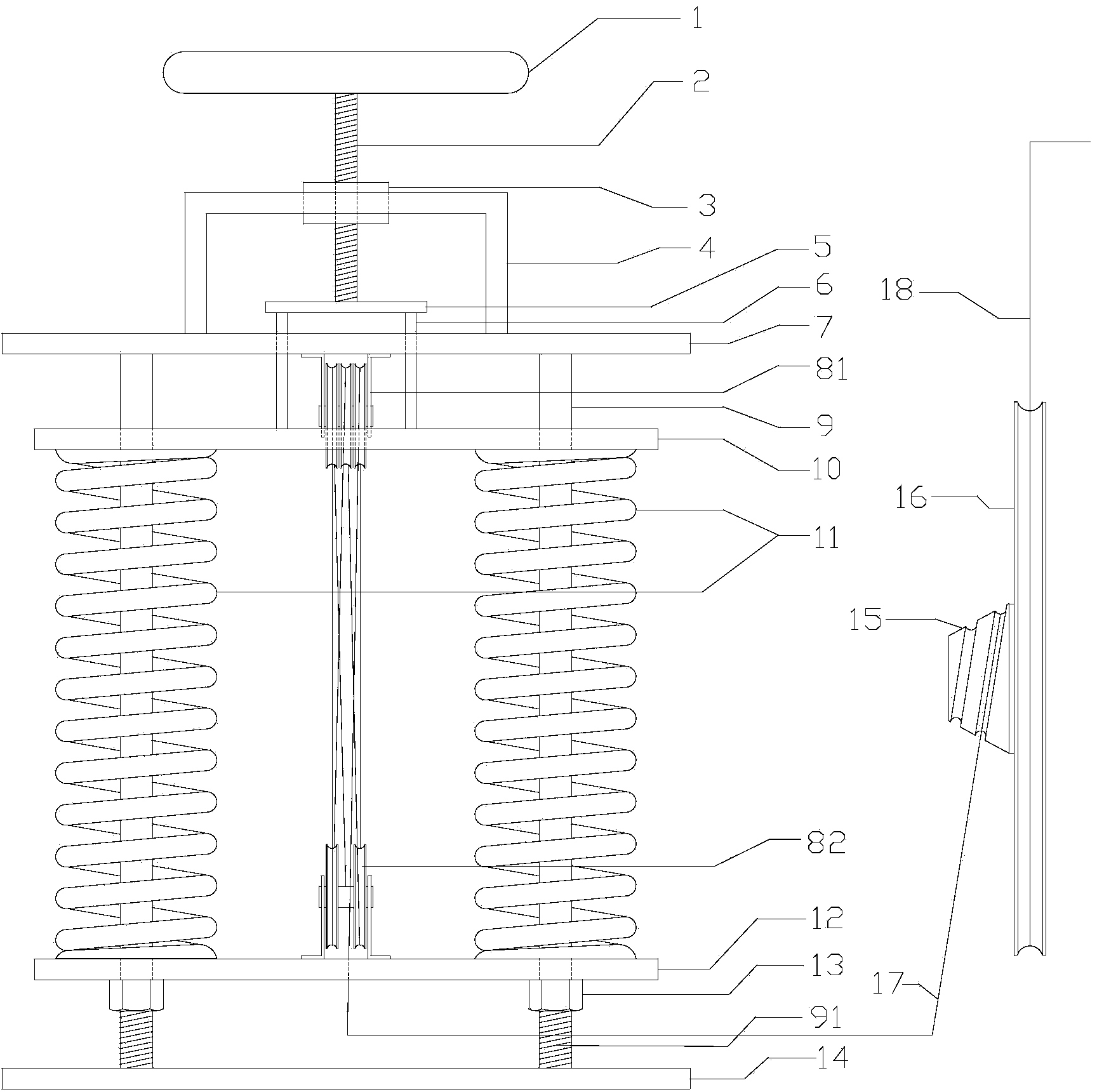
[0016] Such as figure 1 As shown, the embodiment of the present invention is provided with a hand wheel 1, a screw rod 2, a frame connecting nut 3, a gravity scale indicating device frame 4, a plane platen 5, a plane platen guide column 6, an upper frame beam 7, an upper pulley block 81, and a lower pulley block 82. Spring guide post 9, upper spring seat 10, two springs 11, lower spring seat 12, spring guide post connection nut 13, lower frame beam 14, vortex track 15, large round wheel 16, steel wire rope connecting pulley block and vortex track 17, big round wheel and body-building equipment connect wire rope 18.

[0017] The hand wheel 1 is fixed on the top of the screw rod 2, two springs 11 are arranged between the upper spring seat 10 and the lower spring seat 12, and the spring guide post 9 runs through the two springs 11 and the upper spring seat 10 and the lower spring seat 12. , the two ends of the spring guide post 9 are respectively connected with the upper frame b...


PUM


Abstract

The invention relates to fitness equipment, in particular to a fitness equipment spring counterweight balancer which is provided with a hand wheel, a lead screw, a frame connecting nut, a gravity scale indication device frame, a plane pressing plate, a plane pressing plate guiding column, an upper frame beam, a lower frame beam, an upper pulley block, a lower pulley block, a spring guiding column, an upper spring base, a lower spring base, at least one spring, a spring guiding column connecting nut, a vortex track, a large circular wheel, a pulley block and vortex track connecting steel wire rope and a large circular wheel and fitness equipment connecting steel wire rope. The spring is arranged between the upper spring base and the lower spring base. The spring guiding column penetrates through the spring, the upper spring base and the lower spring base, and then the two ends of the spring guiding column are connected with the upper frame beam and the lower frame beam. The gravity scale indication device frame is arranged on the upper frame beam. The upper end of the plane pressing plate guiding column is connected with the plane pressing plate. The lower end of the plane pressing guiding plate penetrates through the upper frame beam and is connected with the upper spring base. The upper pulley block and the lower pulley block penetrate through the upper spring base and the lower spring base and are arranged on the upper frame beam and the lower frame beam. One end of the pulley block and vortex track connecting steel wire rope is fixedly arranged on one side of the lower pulley block. One end of the large circular wheel and fitness equipment connecting steel wire rope is fixedly arranged on the large circular wheel.

Description

technical field [0001] The invention relates to fitness equipment, in particular to a spring counterweight balancer for fitness equipment. Background technique [0002] Most of the existing counterweight devices use counterweight as the load. Since the configuration of the counterweight is affected by many factors such as space, direction and cost, there are disadvantages such as bulky, high cost and high transportation cost, which is not conducive to widespread popularization. For example, the counterweight part of traditional fitness equipment is usually composed of multiple counterweights, and its design can only be carried out by cascading, and the gravity is adjusted according to the increase or decrease of the number of counterweights. The height and gravity adjustment accuracy of fitness equipment Therefore, it is limited, and it is easy to produce the problem that one more counterweight is too heavy, and one less is too light. When some types of fitness equipment ar...

Claims


Application Information

Patent Timeline
Patent Type & Authority Applications(China)
IPC IPC(8): A63B21/05
Inventor 陈佳嘉
Owner 陈佳嘉
Why Eureka
Try Eureka