Fan and fan frame thereof

a fan and fan frame technology, applied in the direction of machines/engines, stators, liquid fuel engines, etc., can solve the problems of affecting the efficiency of the fan, and causing noise during the operation of the fan, so as to increase the speed of the airflow, reduce noise, and increase the air pressure and volume

Active Publication Date: 2008-09-11
DELTA ELECTRONICS INC
View PDF22 Cites 18 Cited by
  • Summary
  • Abstract
  • Description
  • Claims
  • Application Information

AI Technical Summary

Benefits of technology

[0008]In view of the foregoing, the present invention is to provide a fan and a fan frame thereof. Through changes in the design of the fan frame and the airflow guiding structure on the base, the airflow speed can be increased to promote the air pressure and volume. Moreover, the present invention can prevent vortices from occurring at the outlet, so as to reduce noises during the fan operation.
[0011]As mentioned above, in the present invention, the outgoing airflow can be converging by using the airflow guiding structures disposed on the base and the fan frame. Compared with the related art, the fan frame of the present invention can increase the speed of the airflow at the outlet, thereby increasing the air pressure and volume. Moreover, the present invention can prevent vortices from occurring at the outlet so as to reduce noises during the operation of the fan.

Problems solved by technology

However, noises come with high-speed rotations.
Nevertheless, this method is both difficult and impractical.
After the airflow leaves the outlet 102, a vortex is produced at the outlet 102, which results in noises so that a negative effect on the efficiency of the fan is induced.

Method used


Image

  • Fan and fan frame thereof
  • Fan and fan frame thereof
  • Fan and fan frame thereof

Examples


Embodiment Construction

[0016]The present invention will be apparent from the following detailed description, which proceeds with reference to the accompanying drawings, wherein the same references relate to the same elements.

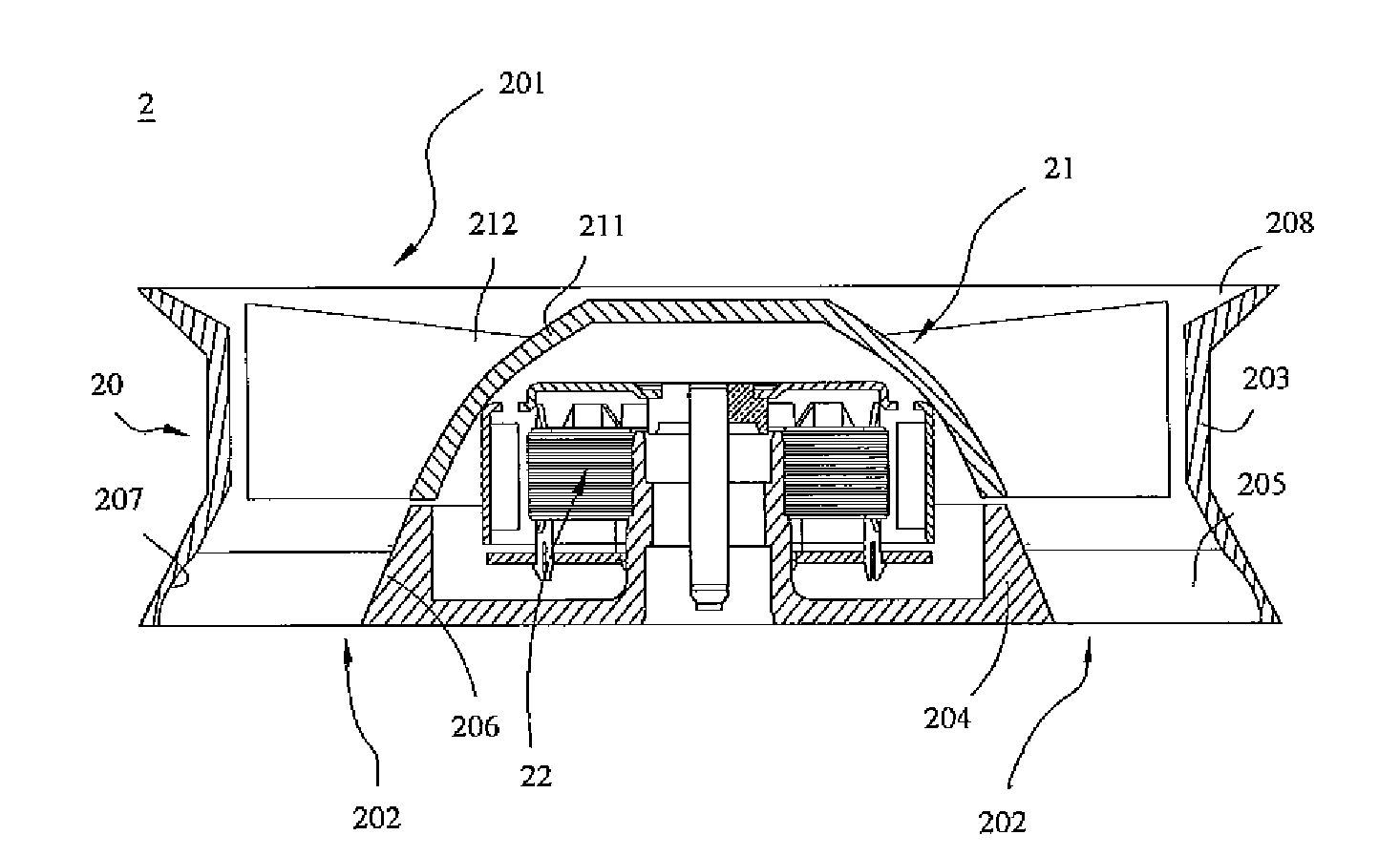
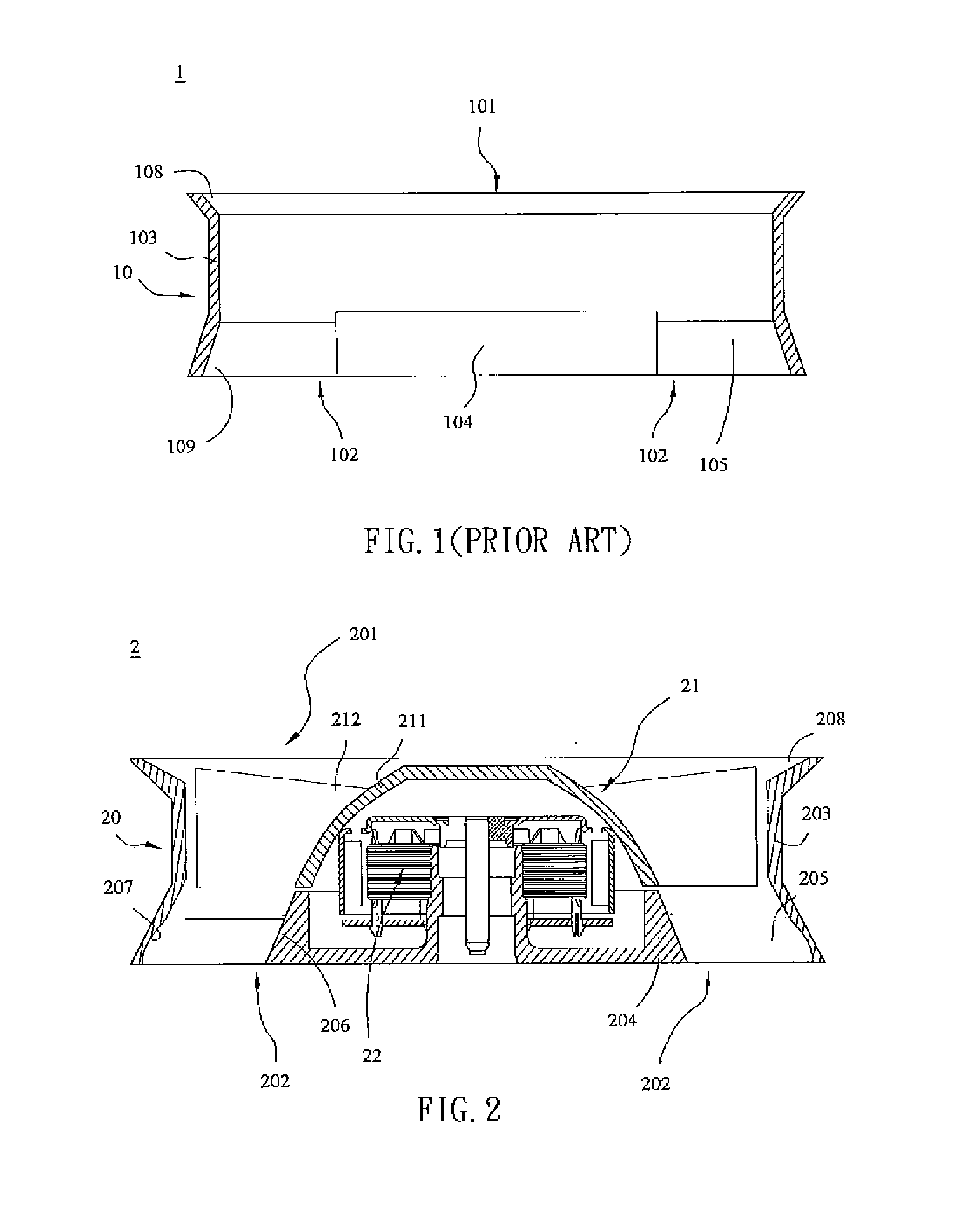
[0017]FIG. 2 is a cross-sectional view of a fan 2 according to an embodiment of the present invention. Referring to FIG. 2, the fan 2 of the embodiment is an axial-flow fan. The fan 2 includes a fan frame 20, an impeller 21 and a motor 22. The impeller 21 and the motor 22 are disposed in the fan frame 20. The fan frame 20 has a housing 203 with a through hole so as to form an inlet 201 and an outlet 202. The fan frame 20 has a roughly square, circular, elliptical or rhombus shape. Besides, the fan frame 20 includes a base 204 and at least one connecting element 205. The connecting element 205 is disposed between the housing 203 and the base 204 for supporting the base 204. In this embodiment, the connecting element 205 can be a rib or a stationary blade. The connecting element 205 can...


PUM


Abstract

A fan has a fan, an impeller and a motor. The impeller is disposed in the fan frame, and the motor is disposed in the fan frame for driving the impeller. The fan frame has a housing, a base and at least one connecting element. The housing has an inlet and an outlet, and the base is disposed in the housing and at the outlet. The connecting element is disposed between the housing and the base. The base has a first airflow guiding structure disposed on the circumference of the base. The housing has a second airflow guiding structure disposed on the inner circumference thereof and adjacent to the outlet. The first airflow guiding structure and the second airflow guiding structure are correspondingly disposed.

Description

CROSS REFERENCE TO RELATED APPLICATIONS[0001]This Non-provisional application claims priority under 35 U.S.C. §119(a) on Patent Application No(s). 096107617, filed in Taiwan, Republic of China on Mar. 6, 2007, the entire contents of which are hereby incorporated by reference.BACKGROUND OF THE INVENTION[0002]1. Field of Invention[0003]The present invention relates to a fan and a fan frame thereof, and in particular to a fan and a fan frame thereof that can lower the noise and increase the efficiency.[0004]2. Related Art[0005]The efficiency of a fan is indicated by the air pressure and air volume that it can generate. To increase the air pressure and volume, one method is to increase its rotation speed. However, noises come with high-speed rotations. To solve this problem, the prior art modifies the design of blades. Nevertheless, this method is both difficult and impractical. In the overall structural design of the fan, changing the fan frame is another way of promoting the fan effic...

Claims


Application Information

Patent Timeline
Patent Type & Authority Applications(United States)
IPC IPC(8): F01D1/02F01D25/24
CPCF04D25/0613F04D29/542F04D29/544
Inventor CHANG, SHUN-CHENHSU, SHUO-SHIU
Owner DELTA ELECTRONICS INC
Why Eureka
Try Eureka